While there is nothing wrong with over-sizing a wire and corresponding fuse (as long as equipment is still protected) it sounds like you are referring to crest factor which really is not necessary. The fuse sees RMS, not waveform....
12% larger is my contribution to the art. Turns out current powering an inverter is not steady-state DC, rather looks like a rectified sine wave. Its Irms value (which heats wires and fuses) is almost 12% higher than its "mean" value, which delivers power.


You are using an out of date browser. It may not display this or other websites correctly.
You should upgrade or use an alternative browser.
You should upgrade or use an alternative browser.
Is there a wire/fuse size chart for 24v?
- Thread starter kenkoh
- Start date
kenkoh
Solar Enthusiast
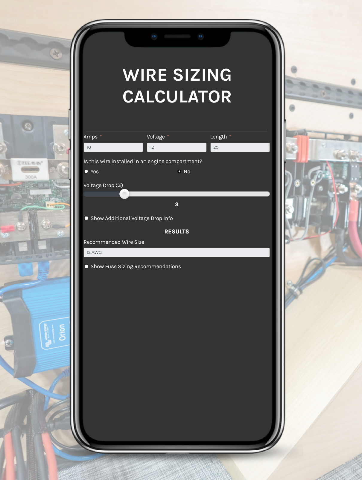
I am going with your recommendation using 4awg and 100a fuse, but is this online calculator way off?It's a 75A load so an 80A fuse is too close and you risk nuisance trips. 75A x 125% = 94A so a 100A fuse would be a good choice. 4AWG wire can safely be fused at 100A so you are good.

Attachments
Hedges
I See Electromagnetic Fields!
- Joined
- Mar 28, 2020
- Messages
- 20,682
While there is nothing wrong with over-sizing a wire and corresponding fuse (as long as equipment is still protected) it sounds like you are referring to crest factor which really is not necessary. The fuse sees RMS, not waveform.
I guess it is crest factor, but I say it is necessary.
Crest factor - Wikipedia
What I'm referring to is that at high current, capacitors in inverter do approximately nothing for 60 Hz current draw by a single (or split) phase inverter. The entire 60 Hz current draw comes from the battery, dropping to near zero twice per cycle. A 3-phase inverter with uniform loading on all phases would not do that.
With say 5kW coming from a 50V battery, that is 100A mean. But it is 111A RMS. If you size your fuse based on the mean current, wattage delivered divided by voltage, it will use up almost half of the 25% oversize normally allocated because the current is a rectified sine wave and will heat the fuse more than DC would have.
This is something I figured out from measurements, have not seen it addressed elsewhere. I do have a habit of figuring out what experts, even teams of experts, have missed.

Battery ripple current
After reading of someone tripping battery breakers at well below rating, I realized that could be due to pulses of current drawn by the inverter. Ideally capacitors would smooth out current draw so high frequency switching pulses and 60 Hz draw all came from the caps, and current from batteries...
 diysolarforum.com
An extra 1.12 multiplier is my contribution to the art.
I'm basing my wire size recommendations off of the Wire Size and Fuse charge provided by Blue Sea System. And then even then I usually recommend one size bigger when near the top of the range. Keep in mind that a pure copper, uninsulated wire can take a lot more amps. But when pushed closer to the limit the wire will be really, really hot. When you add insulation, the insulation is rated to a temperature. Now you need to derate the amperage of the wire so it doesn't get hot enough to melt the insulation. But even then, do you want a wire getting that hot? It may be safe on its own, but I don't want to run my inverter at full load and have the wire getting close to the point where it can boil water. Using bigger wire lets it run a lot cooler.I am going with your recommendation using 4awg and 100a fuse, but is this online calculator way off?
The calculator you reference is not way off on the wire size. Technically, 8AWG meets the ampacity rating. Blue Sea Systems' calculator recommends 6AWG. I suggested 4AWG for the reasons I just outlined.
I don't agree with the fuse size suggested by the calculator you linked. It's only 17% over the load. Technically it should work but most recommendations are 125% times the max load. Taking into possible ripple effect with inverters, 156% is a better calculation. Some people suggest it's best to choose the largest fuse safe for the chosen wire. In many cases larger fuses have less resistance than smaller fuses. As I recall that difference in resistance isn't worth considering when you've already chosen a larger wire than really needed.
kenkoh
Solar Enthusiast
Do I useI guess it is crest factor, but I say it is necessary.
Crest factor - Wikipedia
en.wikipedia.org
What I'm referring to is that at high current, capacitors in inverter do approximately nothing for 60 Hz current draw by a single (or split) phase inverter. The entire 60 Hz current draw comes from the battery, dropping to near zero twice per cycle. A 3-phase inverter with uniform loading on all phases would not do that.
With say 5kW coming from a 50V battery, that is 100A mean. But it is 111A RMS. If you size your fuse based on the mean current, wattage delivered divided by voltage, it will use up almost half of the 25% oversize normally allocated because the current is a rectified sine wave and will heat the fuse more than DC would have.
This is something I figured out from measurements, have not seen it addressed elsewhere. I do have a habit of figuring out what experts, even teams of experts, have missed.
Battery ripple current
After reading of someone tripping battery breakers at well below rating, I realized that could be due to pulses of current drawn by the inverter. Ideally capacitors would smooth out current draw so high frequency switching pulses and 60 Hz draw all came from the caps, and current from batteries...
An extra 1.12 multiplier is my contribution to the art.
I trust you, perfect sense. So I use this formula 1500w/12v/85% x 125% = 184 amps for fusing and wire correct?I'm basing my wire size recommendations off of the Wire Size and Fuse charge provided by Blue Sea System. And then even then I usually recommend one size bigger when near the top of the range. Keep in mind that a pure copper, uninsulated wire can take a lot more amps. But when pushed closer to the limit the wire will be really, really hot. When you add insulation, the insulation is rated to a temperature. Now you need to derate the amperage of the wire so it doesn't get hot enough to melt the insulation. But even then, do you want a wire getting that hot? It may be safe on its own, but I don't want to run my inverter at full load and have the wire getting close to the point where it can boil water. Using bigger wire lets it run a lot cooler.
The calculator you reference is not way off on the wire size. Technically, 8AWG meets the ampacity rating. Blue Sea Systems' calculator recommends 6AWG. I suggested 4AWG for the reasons I just outlined.
I don't agree with the fuse size suggested by the calculator you linked. It's only 17% over the load. Technically it should work but most recommendations are 125% times the max load. Taking into possible ripple effect with inverters, 156% is a better calculation. Some people suggest it's best to choose the largest fuse safe for the chosen wire. In many cases larger fuses have less resistance than smaller fuses. As I recall that difference in resistance isn't worth considering when you've already chosen a larger wire than really needed.
Almost. You use 1500W / 12V / 85% = 150A which is used to determine the wire size. Then 150A x 125% to choose the fuse size.I use this formula 1500w/12v/85% x 125% = 184 amps for fusing and wire correct?
kenkoh
Solar Enthusiast
Ah ok. THANK YOU! Thank you all here.Almost. You use 1500W / 12V / 85% = 150A which is used to determine the wire size. Then 150A x 125% to choose the fuse size.
Hedges
I See Electromagnetic Fields!
- Joined
- Mar 28, 2020
- Messages
- 20,682
I disagree, think NEC and protection of wire requires wire size (ampacity) to be at least as great as fuse rating. Not using a fuse 125% of wire ampacity.
Assuming 12V low-voltage cutoff for battery and 85% inverter efficiency at full load,
1500W / 12V / 85% x 125% x 112% = 206A
Since it is so close, I would round down to 200A fuse, and select a wire of at least 200A ampacity.
That includes the 12% extra for "crest factor", which I was referring to as "ripple factor"
I trust you, perfect sense. So I use this formula 1500w/12v/85% x 125% = 184 amps for fusing and wire correct?
Assuming 12V low-voltage cutoff for battery and 85% inverter efficiency at full load,
1500W / 12V / 85% x 125% x 112% = 206A
Since it is so close, I would round down to 200A fuse, and select a wire of at least 200A ampacity.
That includes the 12% extra for "crest factor", which I was referring to as "ripple factor"
That's not what I'm saying.I disagree, think NEC and protection of wire requires wire size (ampacity) to be at least as great as fuse rating. Not using a fuse 125% of wire ampacity.
We can both agree that a 1500W inverter on a 12V battery means a max load of 150A being pulled from the battery by the inverter.
When I choose a wire size for 150A I'm taking into account both ampacity and voltage drop. I would choose 1AWG at a minimum, 1/0AWG to run a bit cooler.
When picking a fuse you have a range. The smallest fuse is the same as the max load, 150A in this case. The largest fuse is the max fuse rating of the chosen wire. 1AWG can be fused up to 250A and 1/0AWG can be fused up to 300A.
Obviously we don't want to pick a fuse too close the max load since we want to avoid nuisance trips. And of course we don't want to pick a fuse above the max size safe for the wire. This is where the 125% calculation comes in. Take the max load and multiply by 125%. This typically gives a nice value that is between the min and max fuse sizes determined above. In this example we have 150A x 125% = 187.5A. Round up to the nearest available size and you get 200A. And a quick check shows that 200A is safe to use for both 1AWG and 1/0AWG. Perfect.
So no, I do not in any way suggest using a fuse that is 125% of the wire ampacity. I've never said that ever. That would make the fuse pointless since the wire would fail before the fuse even thinks about tripping.
kenkoh
Solar Enthusiast
Thank you everyone, I've learned so much from this thread.
is something burring
New Member
Thank you so much for posting this. I was sort of thinking along these lines but now I found it right and it adds up on paper v x a =w24v fuseing is the same as 12v just that your amperage is half what 12v would be for the same wattage. If you are calculating amps the fuses are the same as they would be for 12v at the same amperage.
24v fuseing is the same as 12v just that your amperage is half what 12v would be for the same wattage. If you are calculating amps the fuses are the same as they would be for 12v at the same amperage.