diy solar

diy solar

Issue with hybrid wind-solar setup

Hogheavenfarm

Regulation Stifles Innovation
Joined
Jun 24, 2022
Messages
432
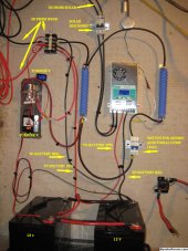
I have been adding a solar component to my wind turbine for the purpose of keeping the batteries charged when we have some non-windy days. (Background - Two 100w solar panels feeding two parallel 12v batteries in parallel with a homebuilt F&P turbine) -
I am getting some unexpected overcharging issues under the following conditions: NO wind, solar only - batteries are reaching 15v and triggering the diversion load solenoid. This is happening every few minutes. The controller for the WIND is set to engage the dump load at 15v (for now, to test the solar controller behavior). The PowMr solar controller is set to 14.4v maximum, 13.8 float.
I expected the solar controller to limit the voltage to 14.4, but this doesn't seem to be happening , instead somehow the batteries go to 15v and trigger the dump load. This dumps for 5 seconds then shuts down. Batteries usually go to 13.6 or so after this, but within a few minutes are back to 15v.
I am attaching a pic in case I have a wiring issue someone can spot. (I know there are no fuses, etc on this yet, still a work in progress).
 

Attachments

  • IMG_1913.JPG
    IMG_1913.JPG
    1.1 MB · Views: 15
When I see weirdness like this I start measuring voltage at various points in the system. EG: Are your batteries really getting to 15v or does your controller just think they are? A loose wire or a bad crimp can cause voltage drop or in this case voltage rise on the controller end.
 
Last edited:
Thanks for looking Oz, The wind controller shows 12.7v and I attached another voltmeter directly to the wind feed (12.8v - NO WIND- turbine locked down) and I can watch those meters climb to 15v+ when the dump load engages. To your point, while they should reflect battery voltage (since there is no input) maybe something else is going on? I will put a meter on the batteries directly as well to capture that. The solar controller doesnt show me battery volts unless I manually cycle through the screens to find it. At the time the dump load was engaging it was showing 20 something volts from the panels (in parallel) and 120 watts (I would rather have it show me amps, but thats more cycling through screens, so about 6 amps).
When you say a bad crimp could cause a voltage rise on the controller end - what exactly do you mean?
I will start poking my meter around all the connections and make a "map" though, especially the wind controller side.
 
Sounds to me as if your solar controller is not working properly.
It should definitely only charge to 14.2v maximum, or whatever the actual charging voltage on the controller is set to.

I would disconnect everything else, and just hook up the solar controller direct to the battery.
If it still tries to go to 15v, and the controller is set to a much lower charging voltage, you controller is definitely faulty.

Check the user manual, or get some information from the internet about your solar controller.
Most if not all solar controllers CAN be tweaked to go as high as 15 volts, and that might also be the problem.
Another possibility is different battery types can sometimes be selected in software, and something other than lead acid battery may be the default battery type setting.
 
Yes, that is a logical next step as well. Battery type is correctly selected for SLA, I programmed it twice so the parameters are correct (checked them again tonight - 14.4 max). Stuck right now as I will have to monitor it while its charging and I have to be at work tomorrow, but I will be able to disconnect the turbine feed at least and wait for the weekend. I could swap back in the old PWM controller for a test as well.
I guess the good news is that nobody sees any dumb wiring issues off the bat.
 
Also check that the digital voltage reading on the controller display actually corresponds to the real battery voltage.
Some of the lower cost Chinese products can be out by a fair bit in calibration.
 
When you say a bad crimp could cause a voltage rise on the controller end - what exactly do you mean?
I will try to explain but I'm often not very good at such things therefore I'm going to invoke Cunningham's law.

So a bad crimp will have a high resistance which to the system will look like an undersized wire. EG: 30 amps on #10 wire will have more voltage drop than a 30 amps on #2 wire. Distance is irrelevant in this example.

Some inverters and charge controllers have an extra set of wires labeled something like "v sense". I'll try go into more detail when I get a chance but you've got some crumbs to let you fill in the story now.
 
Well, predictably the winds of November arrived last night so the turbine was in full operation all night. I will tie it off facing east today to get it out of the north wind. I went out to the barn to see how it was working, nothing unusual, batteries were at 12.8v, so no dumping going on, revs were about 60 rpm so likely not above charging voltage anyway, this unit starts making charging voltage at 100 rpm. Tonight I will throw a breaker in the wind controller lines so I can shut it down and leave it tied off, then just leave the solar on.
With no charging (from any source) going on, all test points were at 12.7v, which is roughly battery voltage, which I expect, but I am ready to test during solar charging as soon as I can get some sun on the panels - (vertical panels hung on east side of barn). May have to wait till teh weekend for that.
 
Just as an update, I added a breaker between the wind controller and the battery and one between the solar controller and the battery, so I can switch between them for testing.
My underlying question concerning the wiring is still unanswered, maybe this helps some, the turbine input (pos) runs to the relay (to allow for diversion load activation), and to the same terminal is attached a positive wire to the batteries (for charging). The (neg) leads run to the battery negative. The controller (wind) is tapped directly off the batteries (the pic I posted may help see this).
My question is simply this - this turbine produces between 0 and 150 volts when in operation. Based on this wiring, it appears that this voltage will be fed directly to the batteries if they are not full. Only when the batteries are full will the diversion load be activated. So say my batteries are at 12.6v (where they are now), and we get high winds that spin me up to 100v or more, am I pumping 100v into the batteries? All the controller does is monitor the battery voltage and divert at 15v.
Sorry I dont have the diagram with me, I will scan it an attach it tomorrow. This is wired exactly as MWAS instructions show.
 
Since that is a homebuilt turbine I can't give you an answer but commercial made turbines with a built in controller or dump load controller won't over charge a battery and will use a brake to prevent the turbine from free spinning once the battery is full or there is no load.

With a homebuilt turbine all bets are off!
 
Agreed, there is no built in controller, seems the controller is additional to the unit and simply runs the dump load (to my way of thinking anyway). Wasnt an issue with the old car batteries in it before, but all new batteries now and I was concerned over how it (actually) operates. It does have a furling mechanism but we have not had high enough winds to test it, the dump load does work but again, not sure how much wattage needs to be there for that. I have it hooked to 600w but no idea what it should be.
 
My question is simply this - this turbine produces between 0 and 150 volts when in operation. Based on this wiring, it appears that this voltage will be fed directly to the batteries if they are not full. Only when the batteries are full will the diversion load be activated. So say my batteries are at 12.6v (where they are now), and we get high winds that spin me up to 100v or more, am I pumping 100v into the batteries? All the controller does is monitor the battery voltage and divert at 15v.
Sorry I dont have the diagram with me, I will scan it an attach it tomorrow. This is wired exactly as MWAS instructions show.
What happens is, that below 12.6v the alternator can contribute nothing, and the turbine rotates freely at some slow speed.

Above the cut in speed, current begins to flow into the battery, the turbine rpm will also rise, but not by much.
The torque required to create the charging current loads the turbine, effectively slowing it down.
More wind, more current, and a further increase in rpm, but the battery limits the rise in actual voltage.

Eventually the battery will reach a maximum safe voltage, and there MUST be some very effective method of limiting or reducing any further current and voltage rise at the battery. That can be done in various ways, but its an absolutely essential feature.

Without a battery fitted, or some kind of voltage regulator in the system, the unloaded turbine direct output voltage can easily reach several multiples of nominal battery voltage.
 
I see, so the battery controls the current flow until its full, then the diversion load controls dumping the excess. Makes sense. Thanks for the explanation.
 
OK, here is the wiring diagram for the wind, I have wired mine exactly like this, but in addition I now have a solar mppt controller in parallel with it (separate feeds to the batteries). I am now ready to perform the testing this weekend, I will try to get a video of whats happening as well.
As a refresher - issue is that when solar is operating and wind isn't, voltage is exceeding 15v and engaging the wind dump load. The mppt is configured as max V - 14.4, float 13.8. It seems the mppt is not cutting off at 14.4 and the dump is kicking in instead. The PowMr mppt is new, it replaced the old PWM controller that I had there. (Orig. pic shows this new controller)
 

Attachments

  • mwas diagram dump  20231110.jpg
    mwas diagram dump 20231110.jpg
    659 KB · Views: 9
@Hogheavenfarm this is all a bit confusing

It seems like your MPPT is shooting the voltage too high , sounds like it could be faulty


Is there a way you can test the mppt completely separately from the wind set up ?

either temporarily disconnect wind charger & dump load OR hook the mppt to a separate system and see if you're still getting the same issue


I know the wind stuff shouldn't be interfering with your MPPT , but it is feasible... so separate testing would eliminate the possibility
 
How many watts is your wind turbine?

Northern Arizona Wind & Sun (dba) NAZ Solar Electric

Those are good people that may be able to help you and very experienced with wind systems.
 
Last edited:
Mppt testing is scheduled for tomorrow, sun willing.
No idea on the watts, it was rewired to a star 4x3coil pattern designed to give a cut in at 48 rpm. I was not able to check the amp output when I built and tested it, that is another test scheduled for the next windy day (possibly this weekend, I see 25 mph winds forecast). I know it puts out 70v at 240 rpm (no load) at 15 mph wind. I didnt get all the test equipment until I went solar last year, so much was missed during the build and early operation in 2021.
The F&P motor in stock configuration is said to run between 0-400 volts and 3-4 amps. 1500watts? Not sure how that might have changed with my mods.
Wind power fluctuates so much and can really hit surge and high volts and watts that it takes a special controller.

My turbine has an internal controller designed for marine applications or I probably would not have wind.
 
Well, I have have to update this thread when I get enough sun to test it. The brief amount of sun that was shining over the weekend got the batteries up to 14.2v but did not go beyond that before a cloud would roll in. I don't see this issue happen until it exceeds 14.4v , so I will update again when I have some results.
 
UPDATE - I think I stumbled on the answer to the overcharging issue. I have programmed many different controllers before, so I am quite familiar with setting the parameters, however I neglected one thing the instructions said to do, since I never had to do it with any other controller. I went through the instructions line by line again, all was correct (14.4v max, 13.8 float) then the instructions say to disconnect everything, connection to batteries, PV etc.and then reconnect them!
I DID NOT do this, I thought they were just trying to make the programming foolproof. Now with teh breakers installed, it was easy for me to turn the unit off, then back on again. Yesterday was very sunny in the morning and I watched the voltage climb to 14.4 and then just stay there (like it should). No dump load activation.
So apparently the parameters I had set had not "taken" because I did not "reboot" the controller. I guess you cannot ignore ALL the chinese instructions, some are pretty accurate!
Now to hook up the inverter and get this show on the road.
 
Back
Top