diy solar

diy solar

JiaBaiDa UP Series BMS (Parallel Packs)

Hi could you tell me how well it works with VRM? Any issues? Does the consumption show in the graphs? Can you view individual cell voltages and alarms?
I am currently in the process of marrying this board with Victron. I will let you know what is shown and what is not. Be patient. You have to be patient with this board, says a dealer in his sales description. 😅The BMS board seems to be very innovative, but the description and operating instructions are rubbish.
 
I am currently in the process of marrying this board with Victron. I will let you know what is shown and what is not. Be patient. You have to be patient with this board, says a dealer in his sales description. 😅The BMS board seems to be very innovative, but the description and operating instructions are rubbish.
Sounds a bit like the seplos boards. Buggy.
 
Hello, I have a JBD BMS 16S 200A of the UP series and have the following problem.
The BMS does not display the charging and discharging current. The PC software shows 0.0A. The transmission via CAN to Victron Cerbo gx is also 0.0A. When the charging current goes to 65A, the BMS shows 2.3A. What to do, Clibration Actual current? Can anyone help me?
Problem solved! A different value must be entered here where "Current mR" is circled in orange. The default is 2.5. I had to enter 0.1. The BMS then displayed the current. I also had to set the current to 0 when the battery was full and no current was drawn from the battery. Calibrate. Now the BMS displays very accurate current values.
 

Attachments

  • Screenshot_20240510_153658.jpg
    Screenshot_20240510_153658.jpg
    577.2 KB · Views: 13
Sounds a bit like the seplos boards. Buggy.
I don't think they do anything to each other. Real Chinese philosophy. Good products and also a very bad service and support. Before JBD I had Daly🙄. With a lot of patience I managed with Victron. But it worked more badly than right. There was no help from the manufacturer. That's why I switched to JBD. It works better but the description is just as bad.
 
Here you will find some very important information about these question marks. Very important values must be entered in these question mark fields. Chinese, how do you think we are going to deal with these question marks? This is where the charging currents and discharging currents for the inverter are set. This is data that is transmitted to Victron via CAN. If only 10A is entered, only a maximum of 10A can be taken from the battery and the rest is taken from the grid.
 

Attachments

  • Screenshot_20240510_152319.jpg
    Screenshot_20240510_152319.jpg
    424.7 KB · Views: 16
Last edited:
Thanks to Wuerzburger, who found this new JBD tool. With the new JBD tool, the question marks have been translated into English. Now I have been able to solve another problem.
 

Attachments

  • Screenshot_20240510_153031.jpg
    Screenshot_20240510_153031.jpg
    406.8 KB · Views: 15
Hi could you tell me how well it works with VRM? Any issues? Does the consumption show in the graphs? Can you view individual cell voltages and alarms?
I have been able to solve all the problems so far. The JBD BMS works much better than my old Daly BMS with Victron. I have a Cerbo GX no Venus Os. VRM recognizes the battery as a Pylontech product. Apparently the CAN protocol is the same. Charging and discharging currents are displayed. The charging voltage and power. Parameters are also shown such as the max. set charging current and discharging current. Various alarms, if there are any. The 16 cell voltage of a pack is not displayed. Since I have not connected another battery pack yet, it is of course not displayed. But I think as soon as I connect the second battery, it will also be displayed. For me, the battery information displayed by the BMS in the VRM is enough. The BMS works very well with Victron. I am very satisfied and do not need to replace it.
 
Hey folks, I am trying to figure something how here, maybe someone can help. I have the same BMS well its the 100A-200A version. JBD-UP16S010-L-16Sl100A-B-R-C.

I noticed even on your screenshots that the Capcity Config for 80% is set to 3.3V. Though under the Basic Protocol Parameter Information its set to Max Overvoltage 3650 (3.65V) and 3380 (3.3) release.

I changed the Capcity information that was default set to like 100000. In my case the batteries are 74Ah so I set it to 74000maH. That edited the cycle capacity automatically. I'm not sure what that value should be.

What troubles me is my battery pack 16S LifePo4 will only charge to 3330mv (3.3v) which I think is being controled/limited by the 80% capacity number under Capacity information. However that area is completely greyed out. I can't edit it. I want to charge my batteries to 3.5v. Even under Capacity information it says "Full Voltage 3550mv". So I don't understand why the BMS is capping charging at 3.3V. Anyone know how to change this behavior?

Also for those asking how to connect via RS485, buy the waveshare RS485 converter, take an ethernet cable, cut the end off one end, and connect. There are three spots for wires on the waveshare adapter. The far left one gets the white wire that is wrapped around the orange wire. The second (middle) spot gets the orange wire, the 3 and last hole you leave empty. The rest of the ethernet wires are not needed. Plug the waveshare converter into your computer and the ethernet cable jack into the BMS port and you can connect to JBDTOOLS no problem.

Anyways if anyone can shed light on how I can get my batteries to 3.5V and not cut off at 3.3V that would be super helpful.
 

Attachments

  • 6.png
    6.png
    1.1 MB · Views: 14
  • 4.jpg
    4.jpg
    44.1 KB · Views: 12
  • 5.jpg
    5.jpg
    41.3 KB · Views: 10
  • 3.jpg
    3.jpg
    75.9 KB · Views: 14
  • 7.png
    7.png
    1.3 MB · Views: 15
Last edited:
Thanks @Eugenjbd I will download that version and give it a try. I have so many versions of their software lol. Hopefully this one connects, lots of times I get a garbled mess of ascii. I did order the "official" cable from JBD to connect from the BMS to the computer from Ali-express so it'll be awhile before it get it. Maybe that will make some difference, maybe not. I based my connection method on one of the more respectable YouTuber's out there. If this software works man I will owe you a cold beer! :)

Gotta go grab my other laptop to give it a try.

Cheers,
Cyberfed
 
Danke 
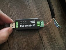
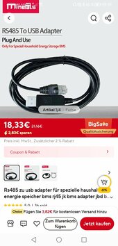
@Eugenjbd Ich werde diese Version herunterladen und es ausprobieren. Ich habe so viele Versionen ihrer Software, lol. Hoffentlich stellt dieser eine Verbindung her, oft bekomme ich ein verstümmeltes Durcheinander von ASCII. Ich habe das „offizielle“ Kabel von JBD für die Verbindung vom BMS zum Computer bei Ali-Express bestellt, daher wird es eine Weile dauern, bis es verfügbar ist. Vielleicht macht das einen Unterschied, vielleicht auch nicht. Ich habe meine Verbindungsmethode auf einen der angeseheneren YouTuber da draußen gestützt. Wenn diese Software funktioniert, schulde ich dir ein kühles Bier!:) :)

Ich muss mir unbedingt meinen anderen Laptop schnappen, um es auszuprobieren.

Prost,
Cyberfed
I use this RS485 to USB cable. However, it only works in the RS485 socket next to the CAN. The RS 485 in the double pack for the battery paralell connections does not work with it.
 

Attachments

  • Screenshot_20240513_093923_com.alibaba.aliexpresshd.jpg
    Screenshot_20240513_093923_com.alibaba.aliexpresshd.jpg
    88 KB · Views: 1
So its working now! I actually already had that version of the software but it was displaying a garbled mess. I decided to plug it into the RS485 next to the CAN like you mentioned above and it connected, 99% of readable there were still a funky symbols. But I was able to modify the parameters and left it charging. The batteries surpassed the the 3.3 voltage and it is now closer to 3.5. One battery hit 3.5 which triggered the BMS to stop but the others are at 3400-3490 give or take. Any tricks to get them to be more balanced? Previously at the settings it had stock (which I did save) the batteries were always within x.xx3 of each other give or take. They balanced nicely, same on discharge. Curious why the disparity now. I wonder if somehow I need to change my settings some more.

I ordered that exact cable from Ali-Express from the official JBD store. Waiting on it to arrive to see if that makes any difference.

Thank you!!!
 
Well I must say that JBD's support via Ali-express was actually darn good! They gave me the password (wrong one the first time but hey it happens) to the latest software so I could log in as "production manager" and make changes to any setting in the BMS using the very latest version of the software they make. Charge_POW_2024xxxx something like that is the .exe The password in case anyone wants it at least for my model is "JBD2023" without the quotes.

As I am a bigtime newbie with LFP chemistry. I think my problem thinking I wasn't getting a "full charge" was a two part error. #1 The AC charger I'm using has two 48V charging profiles for LFP, one is standard the other is "high speed" other than a current difference I didn't think there was much difference. Well I read the manual (imagine that) some more and found that the standard profile charges to the 80/20 settings. I just finished up building yet another 16S 48V system and this time I set the AH on the BMS correctly before setting it to "fast" charging, and while the battery voltage is very slowly creeping up from 3.2 - 3.3 it IS going up, further than before (until I started hacking the BMS). The SOC indicator seems in line with what the charger is putting out in terms of historical data and the SOC LED's seem to be following the AHs. So its not so much about the voltage itself is it?

You can answer if you want (would appreciate it) but I need to just read up on LFP charging profiles and understand them a bit better. Didn't help that my charge was deliberately doing 80/20. I was thinking the batteries HAD to be at say 3.5 to get all the juice they can provide, seems like they can sit at 3.2V and still be 100% full. I'm learning...the hard way...sigh. If you are curious why I'm charging via AC, I always charge a brand new pack with a AC charger designed for LFP 48V then after the first charge it goes out and gets charged via solar. But since I was testing all this hacking around with the BMS, it was easier for me to use the AC charger.
 
Last post I promise. I got in the mail from Ali-Express the "official" JBD cable to connect to the BMS. Works great and is much faster and reliable than the one I made myself out of an ethernet cable. It even told me there was a software update and updated it. That nice speed with the ability to log in and change any setting makes it a nice BMS, though I wish the balancing methodolgy was better, however when ever I charge or discharge my cells even if there is still like a 50ma delta, they fall in line very quickly down to 3ma. I'm just the kinda person that wishes that when I charged it up full it would be close to that. Not so much, oh well, if I leave it on long enough it gets down to the 30mA difference the default setting is set for.
I am going to go in and change the "Short Circuit" amperages setting on it. It's set to 1400A, and I personally feel that if there is a short or even a problem starting to brew, shut it down. I'm going to drop that number down to like 300A.
Cheers.
 
Can you explain which parameter is responsible for the full battery charge and stops the battery charge? I have a Deye SUN-12K-SG04LP3-EU inverter and a JBD UP16S010. When I charge from the sun, according to my settings, I thought that the cell would reach Full voltage = 3400 and stop. But I constantly get the Cell OVP error from the battery (if it goes over 3500) or Pack OVP (if it goes over 56000), only after that Deye stops charging the battery. And according to the settings, until the cell drops below 3400, it should not give a charge, and Deye gives a charge again in 2-3 seconds and so on constantly. Every 2-10 seconds CHG\Protect\DISCHG, although in my opinion it should be in the Stanby position when the battery is 100% charged. This can be seen in the logs. Please help, maybe someone who has encountered a similar problem.
 

Attachments

  • log.jpg
    log.jpg
    704.7 KB · Views: 10
  • err.jpg
    err.jpg
    50.8 KB · Views: 9
  • set.jpg
    set.jpg
    147.6 KB · Views: 9
  • log2.jpg
    log2.jpg
    291.1 KB · Views: 8
Can you explain which parameter is responsible for the full battery charge and stops the battery charge? I have a Deye SUN-12K-SG04LP3-EU inverter and a JBD UP16S010. When I charge from the sun, according to my settings, I thought that the cell would reach Full voltage = 3400 and stop. But I constantly get the Cell OVP error from the battery (if it goes over 3500) or Pack OVP (if it goes over 56000), only after that Deye stops charging the battery. And according to the settings, until the cell drops below 3400, it should not give a charge, and Deye gives a charge again in 2-3 seconds and so on constantly. Every 2-10 seconds CHG\Protect\DISCHG, although in my opinion it should be in the Stanby position when the battery is 100% charged. This can be seen in the logs. Please help, maybe someone who has encountered a similar problem.
I have the same combination (DEYE SUN 12K and 5 Packs with JBD BMS) - I think you should set values in the "Other" Section. Go to "Inverter settings" and set the "Chg Vol" (and also the other values according to your needs).
If you want to charge your cells to 3,6 V the the adequate "Chg Vol" is 16 * 3,6V= 57.6 V (or a little bit higher like 57.7 / 57.8) - with this the battery pack will not go to this on / off situation.

In Other section I have Chg Vol = 57.6 , but after change this volume to 57.5, after few seconds it becomes 57.6 again. I should set 3.6 per cell, I cant charge to 3.5? Can you send yours settings in MJBDTools section Parameter?

1717594394274.png
 
Hi.
Anybody know how to change battery capacity in JBD Tools? I have 305 AH bank of batteries controlled by UP16S010 200A BMS. JBD Tools shows 200 AH capacity of my batteries. How I can set up to real capacity?
 
G day good folks.

I have The 200A version of this bms installed on 340ah lifepo4 16s battery. Connected to 3phase Deye 12ke hybrid inverter.

I have 3 battery in parallel both terminals (50mm2 cable) and The RS485 parallel port (rj45 cables)

Connected to the Deye Inverter via CAN port. Works 100% without any problems.

Issue is, I am using solar assistant on Orange Pi.
LTD.

Under battery = use inverter values, this works perfect, Volt, wattage, soc etc.. Soc reads off the single battery/bms Via CAN. Which is good enough as soc across The 3 battery is same.

But I now want to be able to see full bms details, voltage of each cell. Etc.. I want Solar assistant to connect to display all 3 battery info.

Has anyone done this successfully?
For me the best I got was using a usb rs485-rj45 cable plugged Into RS485 (next to CAN port).

I can only ever connect to one bms at a time via the below method. Which there after the bms data shows in Solar Assistant.

In Solar Assistant, under settings > battery = select "USB serial S232/485".

One thing I worked out.. JUMPER PIN must be set to slave 1 (not master) other pin arrangement does not work.


If Selecting "USB JBD" it doest work.

Any ideas?
 

Attachments

  • Screenshot_2024-06-25-21-26-24-35_99c04817c0de5652397fc8b56c3b3817.jpg
    Screenshot_2024-06-25-21-26-24-35_99c04817c0de5652397fc8b56c3b3817.jpg
    31.2 KB · Views: 2
G day good folks.

I have The 200A version of this bms installed on 340ah lifepo4 16s battery. Connected to 3phase Deye 12ke hybrid inverter.

I have 3 battery in parallel both terminals (50mm2 cable) and The RS485 parallel port (rj45 cables)

Connected to the Deye Inverter via CAN port. Works 100% without any problems.

Sorry, can I see yours screenshot from jbdtools (Parameter tab), I have problems with OVP errors :( with the same pack (DEYE SUN 12K + 2 200A JBD)
 
In Other section I have Chg Vol = 57.6 , but after change this volume to 57.5, after few seconds it becomes 57.6 again. I should set 3.6 per cell, I cant charge to 3.5? Can you send yours settings in MJBDTools section Parameter?

View attachment 219881
Sorry I was "offline" due to another project.
If you want to "end" charging with an average of 3.5 Volt per cell: 56.0 Volt should be the right setting (3.5*16=56).
Do you still want my settings? I have two packs with 105AH cells (with 100A BMS), two packs with 230AH cells (with 200A BMS) and one with 304Ah cells (with 200A BMS) - what are the settings you are looking for? I attache (no guarantee - your risk) my stettings from the 304Ah pack.

And the BMS-SW seems to "round" the values up or down - the same here with me ;-)
 

Attachments

  • JBD-304Ah-200A.zip
    965 bytes · Views: 3
Last edited:
Hi.
Anybody know how to change battery capacity in JBD Tools? I have 305 AH bank of batteries controlled by UP16S010 200A BMS. JBD Tools shows 200 AH capacity of my batteries. How I can set up to real capacity?
You can use the "old" SW-Version - there it can be changed directly - or the new version (then you have to log in (Account) as product manager with the password JBD2023). In the parameters section you can change the capacity (Nominal Capacity).
 
Sorry I was "offline" due to another project.
If you want to "end" charging with an average of 3.5 Volt per cell: 56.0 Volt should be the right setting (3.5*16=56).
Do you still want my settings? I have two packs with 105AH cells (with 100A BMS), two packs with 230AH cells (with 200A BMS) and one with 304Ah cells (with 200A BMS) - what are the settings you are looking for?
And the BMS-SW seems to "round" the values up or down - the same here with me ;-)
 
Sorry I was "offline" due to another project.
If you want to "end" charging with an average of 3.5 Volt per cell: 56.0 Volt should be the right setting (3.5*16=56).

Thanks for settings. I understand now, why I have many OVP and POVP errors, Deye charge voltage in lithium mode always 57.6, But I want to charge only for 56.0. And I cant set this settings nowhere. When set "Chg Vol" on "Other" tab in JBDTools, after few second it becomes again 57.6. I can't believe the only thing that stopping Deye for charge battery is only the OVP and POVP settings in BMS? Not "Full set voltage" or other, only OVP and POVP errors. But another problem, Release is not working well in JBD BMS. After OVP (3500), BMS must wait until 3400 (in my settings) but after few seconds it begun charge again, and again OVP then loop.

It was great if Deye have setting "Max Battery Charge % from Sun", wrote to their support, the answer is below.
 

Attachments

  • Screenshot - 2024.06.26 , 16_17_07.png
    Screenshot - 2024.06.26 , 16_17_07.png
    53 KB · Views: 4
  • Screenshot - 2024.06.26 , 16_11_56.png
    Screenshot - 2024.06.26 , 16_11_56.png
    53.2 KB · Views: 4
  • Screenshot - 2024.06.26 , 16_30_38.png
    Screenshot - 2024.06.26 , 16_30_38.png
    34.3 KB · Views: 4
Last edited:

diy solar

diy solar
Back
Top