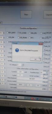
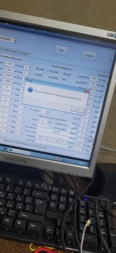
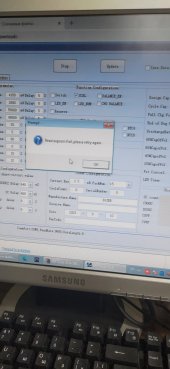
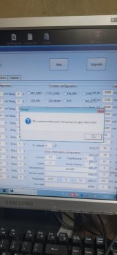
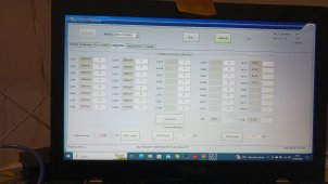
Модель была спроектирована по размерам, указанным в инструкции. Спасибо за прошивку, но есть другая проблема. ПК не подключается к BMS. Пробовал rs 485 также через UART, результат отрицательный. Выдает такие ошибки! кстати подскажите пожалуйста стабильную версию программы которая будет корректно работать v2.7 на виндовс 7 часть информации размытавиклав рішення. Поделитесь файлом модели для 3d друку?


You are using an out of date browser. It may not display this or other websites correctly.
You should upgrade or use an alternative browser.
You should upgrade or use an alternative browser.
JiaBaiDa UP Series BMS (Parallel Packs)
- Thread starter jyauxi
- Start date
Если найду, обязательно поделюсьвиклав рішення. Поделитесь файлом модели для 3d друку?
Не ви у мене в ютубі питали про підключення ? Кілька тижнів тому.Модель была спроектирована по размерам, указанным в инструкции. Спасибо за прошивку, но есть другая проблема. ПК не подключается к BMS. Пробовал rs 485 также через UART, результат отрицательный. Выдает такие ошибки! кстати подскажите пожалуйста стабильную версию программы которая будет корректно работать v2.7 на виндовс 7 часть информации размыта
На рс485 пару з даними а/б перекидали?
Скоріше за все я! Так перекидав нічого не змінилося. UART теж намагається передати пакет файлів але безуспішно!Не ви у мене в ютубі питали про підключення ? Кілька тижнів тому.
На рс485 пару з даними а/б перекидали?
Wuerzburger
New Member
So let me follow - here is version 2D...Hi, yes i have solution. it is very simple i updated the firmware on my board via rs485...
and I don't understand, here some write that they have received an update, but no one shares, why are you here? rhetorical question...
have the firmware file and instructions attached (v2.4)
whatever you do with it is at your own risk!!!
Attachments
Wuerzburger
New Member
I use this RS485 cabel (from aliexpress) and it works perfect. You should plug it in the rs485 port next to the can-port (not one of the two 485-ports that are intended to parallel batterysСкоріше за все я! Так перекидав нічого не змінилося. UART теж намагається передати пакет файлів але безуспішно!
 )
)Domenicos1890
New Member
CalibrationCao qualcuno ha un manuale d uso e settaggi del bms , vi sono delle voci che non si riescono a tradurre in inglese
") if you have different voltages on battery and on BMS. And currents too
if you have different voltages on battery and on BMS. And currents tooRobbert
Solar Enthusiast
Is it possible to connect this BMS to Solar Assistant with the new firmware?
Could you please show me the pin-out for RJ45? I already have the converter, but I can't find a pinout for the rs485 portI use this RS485 cabel (from aliexpress) and it works perfect. You should plug it in the rs485 port next to the can-port (not one of the two 485-ports that are intended to parallel batterysView attachment 164059)
Or send me in a private message a link for this cable
---UPDATE---
I found
Last edited:
Wuerzburger
New Member
I also have two packs - I use two cables (each BMS is connected with its own cable to an USB-Port on the PC) and switch the COM-Port and Master / Slave in the software. I think there is no communication "PC - slave battery" when connected to the master battery (over the RS485-connection between the two cells).Hello anyone can help me ?
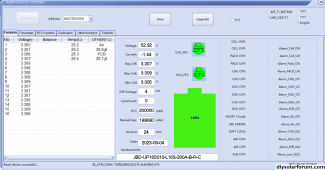
I had JBD-UP16S010-L16S-200A-B-R-C Series 2 units.But I have any problem for parallel communication . How can i check in software.It communicate or not.
I'm trying to create DIY monitoring with esphome, but I can't receive any response from BMS.
I'm using the UART protocol and commands from the original doc.
Maybe somebody has a positive experience with that or knows some helpful project, it would be great.
I'm using the UART protocol and commands from the original doc.
Maybe somebody has a positive experience with that or knows some helpful project, it would be great.
Paul_in _Berkeley
New Member
- Joined
- Dec 9, 2020
- Messages
- 14
Translation: Hello, does anyone have a user manual and settings for the BMS, there are some entries that cannot be translated into EnglishCao qualcuno ha un manuale d uso e settaggi del bms , vi sono delle voci che non si riescono a tradurre in inglese
Take a look at https://github.com/smaksimowicz/esphome-jbd-bmsI'm trying to create DIY monitoring with esphome, but I can't receive any response from BMS.
I'm using the UART protocol and commands from the original doc.
Maybe somebody has a positive experience with that or knows some helpful project, it would be great.
Wuerzburger
New Member
Here are the docs I collected regarding JBD SW and Hardware - maybe you can find the info you are looking for ...Translation: Hello, does anyone have a user manual and settings for the BMS, there are some entries that cannot be translated into English
Attachments
I checked with my BMS, but it doesn't work, unfortunately
Debugging looks like this https://monosnap.com/file/Slgrr3uWLeiwBPd7ZImzWUypOfxzUG
I'm using MAX485 UART-RS485 converter and ESP32 (also checked with Wemos d1 esp8266)
This converter works correctly for reading telemetries from the Deye Inverter.
p.s. On PC it works with bms tools application v2.7 only, not with higher version or else bms tools (converter RS485 with CP2102).
monosnap.com
Monosnap screenshot tool for Mac and PC with own cloud storage. Take screenshots, record videos and upload files directly to the cloud. Just in one click.
 monosnap.com
From logs it seams that BMS is not responding for proper command. I'm using UART TTL to RS485 CIA00485T module. I'm powering this module with 3.3V direcly from esp32 board. Plase check also dip swith configuration - you have to set them all to 0 according to logs.I checked with my BMS, but it doesn't work, unfortunately
Debugging looks like this https://monosnap.com/file/Slgrr3uWLeiwBPd7ZImzWUypOfxzUG
I'm using MAX485 UART-RS485 converter and ESP32 (also checked with Wemos d1 esp8266)
This converter works correctly for reading telemetries from the Deye Inverter.
p.s. On PC it works with bms tools application v2.7 only, not with higher version or else bms tools (converter RS485 with CP2102).

monosnap.com
Monosnap screenshot tool for Mac and PC with own cloud storage. Take screenshots, record videos and upload files directly to the cloud. Just in one click.
Also check your esp32 uart connections - they must be conected straight rx(esp)->rx(rs485 module) tx(exp)->tx(rs485 module)

Last edited:
From logs it seams that BMS is not responding for proper command. I'm using UART TTL to RS485 CIA00485T module. I'm powering this module with 3.3V direcly from esp32 board. Plase check also dip swith configuration - you have to set them all to 0 according to logs.
Also check your esp32 uart connections - they must be conected straight rx(esp)->rx(rs485 module) tx(exp)->tx(rs485 module)
Got it, thanks.
I think that my problem is related to flow control, and I should use
Code:
flow_control_pinAnyway, I ordered the same converter with auto-flow direction control.
--- UPDATE ---
Yeah, it works with a flow control pin. It's weird why the original author decided to skip this option
very thanks for the git link @arH1983
Last edited:
ledz0
New Member
Hello guys!
I have 2 items these BMS and I want connect parallel.
I have issue with parallel connection.
There was connected 2 BMS RS485(Parallel port) - RS485(Parallel port), for slave BMS i put address (1000).
I can't connect to slave BMS via master BMS from PC.
And LCD dispay wrote in menu PackPara->"This content is not settable"
Can you share diagram how to configure parallel connection?

Similar threads
- Replies
- 18
- Views
- 392
- Replies
- 6
- Views
- 1K
- Replies
- 1
- Views
- 176
- Replies
- 22
- Views
- 2K