diy solar

diy solar

JK 4S 200A BMS

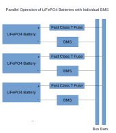
If parallel battery packs are required, the same voltage can reduce the chance of failure,
But it's hard to achieve,
Or add a discharge diode in each battery pack, which is the way we are currently considering

How is the same voltage hard to achieve? 90% of the charge curve is at the same voltage or only 100mv difference. Also as packs are charged and discharged that voltage will even out.

It seems many here have real world experiences that differ from your statements.
 
How is the same voltage hard to achieve? 90% of the charge curve is at the same voltage or only 100mv difference. Also as packs are charged and discharged that voltage will even out.

It seems many here have real world experiences that differ from your statements.
I think what is missing is technical explanation of exactly what the failure mode is that is resulting in manufacturer of the JK BMS saying it is not recommended. If we knew that we could understand better what the risks are and if they are even applicable to us.
 
For instance. A and B batteries are in parallel. At this time, the battery voltage is 72V. If the A batteries are discharged for some reason (battery consistency, temperature, current, etc.), A batteries cannot be discharged at this time, B batteries discharge normally. When B batteries are discharged to 60V, A batteries break down and resume discharging. At this time, the voltage of A batteries is still 72V, B batteries have reached 60V, and when A batteries resume discharging for an instant, Equivalent to 72V and 60V directly parallel. In this case, a short circuit will occur directly. The same is true when charging.
Another problem is that. Over time, the consistency of batteries becomes worse and the difference between the two batteries becomes greater. That's why I've always emphasized the importance of battery consistency.
Parallel connection can always be supported if the two BMSs do not have any protection during parallel connection and keep the voltage parameters consistent (same voltage/same configuration for both BMS parameters).
 
While I agree that this can technically be an issue with certain chemistries, there are a few caveats I want to point out.

1) Because the flat curve of LiFePO4, you would have to have extreme conditions for this to be a problem. Even batteries that are at 50% delta in state of charge won't have a large voltage difference. And even then if there is a voltage difference, the current when paralleling these is rather small, because the voltage delta is not sustained for long: it takes very little to drop from 3.6V to 3.4V. This is not the case with all chemistries, but with LiFePO4 which most, if not all, are using, this should not be an issue.

2) As I mentioned many times, put a fast acting Cass T fuse on each battery pack. That way, if there should be a current produced in such a way when paralleling packs that is outside the range of what the BMS can handle, for whatever reason, it is shut down immediately.

I understand @Nami 's point of view from a vendor/warranty position, but if one keeps a system operating within BMS parameters and have another device protect the pack in case of extraordinary circumstances, and if you're running LiFePO4, you should be fine. By the way, I put my money where my mouth is: I've been running two 48V packs in parallel for two years, and I'm adding two more soon. All of them with a JK BMS.
Not all customers have a good technical base.
If everyone operates in parallel and does not have good protection for the BMS and battery pack,
BMS will inevitably fail.
Then in the future, the reputation of JK BMS will also decline. Compared with sales, we pay more attention to product quality and user evaluation. Thank you
Your plan is good. I told the engineer that the engineer is sure of your plan. If a fuse breaks, you only need to replace it. This is the most economical and practical plan.
Diodes are a foolproof solution. But it's more expensive,
We recommend this to our customers and modify the product description. Thank you for your suggestion.
 
While I agree that this can technically be an issue with certain chemistries, there are a few caveats I want to point out.

1) Because the flat curve of LiFePO4, you would have to have extreme conditions for this to be a problem. Even batteries that are at 50% delta in state of charge won't have a large voltage difference. And even then if there is a voltage difference, the current when paralleling these is rather small, because the voltage delta is not sustained for long: it takes very little to drop from 3.6V to 3.4V. This is not the case with all chemistries, but with LiFePO4 which most, if not all, are using, this should not be an issue.

2) As I mentioned many times, put a fast acting Cass T fuse on each battery pack. That way, if there should be a current produced in such a way when paralleling packs that is outside the range of what the BMS can handle, for whatever reason, it is shut down immediately.

I understand @Nami 's point of view from a vendor/warranty position, but if one keeps a system operating within BMS parameters and have another device protect the pack in case of extraordinary circumstances, and if you're running LiFePO4, you should be fine. By the way, I put my money where my mouth is: I've been running two 48V packs in parallel for two years, and I'm adding two more soon. All of them with a JK BMS.
If you don't mind, can you share your plan?
I think this might help some customers. Thank you.
This is more effective and convenient than our word explanations
 
So as a vendor, the recommendation of not running 2+ BMS in parallel is to “prevent stupid” and the customer blaming JK for their stupidity.

?

Alas I should speak so harshly, I remember a saying about “making thinks idiot proof” I maybe the next idiot.
 
While I agree that this can technically be an issue with certain chemistries, there are a few caveats I want to point out.

1) Because the flat curve of LiFePO4, you would have to have extreme conditions for this to be a problem. Even batteries that are at 50% delta in state of charge won't have a large voltage difference. And even then if there is a voltage difference, the current when paralleling these is rather small, because the voltage delta is not sustained for long: it takes very little to drop from 3.6V to 3.4V. This is not the case with all chemistries, but with LiFePO4 which most, if not all, are using, this should not be an issue.

2) As I mentioned many times, put a fast acting Cass T fuse on each battery pack. That way, if there should be a current produced in such a way when paralleling packs that is outside the range of what the BMS can handle, for whatever reason, it is shut down immediately.

I understand @Nami 's point of view from a vendor/warranty position, but if one keeps a system operating within BMS parameters and have another device protect the pack in case of extraordinary circumstances, and if you're running LiFePO4, you should be fine. By the way, I put my money where my mouth is: I've been running two 48V packs in parallel for two years, and I'm adding two more soon. All of them with a JK BMS.
I found this extreme test that Andy did with paralleling cells at different voltages to be very interesting.
 
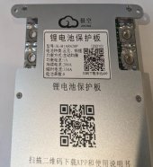
The BMS arrived yesterday evening. It has a paper label stating it to be a 'JK-B1A8S20P', but it is a heating circuit model per Nami's description in post #1.

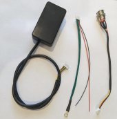
Although labeled for 1A balance current, it might actually be the "2A" model, now for sale here: 2A version with heat, at Aliexpress "Hankzor BMS Store". I can test to obtain that limit, using an appropriate resistor load on just one cell within the managed battery pack. the package came with a dual temperature sensor interface already attached on the BMS. 3 accessory attachments were also provided:
  1. A BMS push-button power switch;
  2. A small 'monitor' device;
  3. The new heater port cable assembly.
I did not receive any device or cable which can utilize the RS-485 port. A GPS port is also present, but J-K has not yet created a GPS device to use it. The 'push-button power switch' and the 'monitor device' both connect to the same 6-pin header port on the BMS unit. They can't be connected at the same time. The power switch cable contains 4 wires, while the monitor uses all 6 wires BMS port pins.

The heater port cable provides a small black wire, presumably a "ground", and a red cable, presumably running at battery voltage. I don't know whether it is actually necessary to connect those wires to anything, Or whether they are provided as "test leads" for optional use while the heater interface is being used. The other 4 wires, green in color, are bonded to a single shared lug. I suspect this to be the shared "switched" heater power link, although the wire color is somewhat misleading to a resident of the USA.

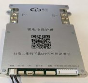
I can test for correct wiring of this interface, if Nami does not have time to reply here. I can do some testing on Monday. 3 attached photos show the accessories, the somewhat incorrect label, and the front of the BMS, with ports shown. (I left the monitor upside down in the photo, the LED screen is shiny and there is a small button on it). Android App installation from the QR code was easy and uneventful (assuming that Version 4.6.5 was the one to select).
 

Attachments

  • front-with-connector-ports.jpg
    front-with-connector-ports.jpg
    214.3 KB · Views: 32
  • back-label.jpg
    back-label.jpg
    184.3 KB · Views: 32
  • accessories-scaled.jpg
    accessories-scaled.jpg
    185.3 KB · Views: 30
I found a manual that Nami uploaded to the documents which has the Chinese instructions and an English translation after it but have not had the time to fully read it. You can probably find some of your answers there. Where did you find the CR code and were the instruction for it in English?
 
The BMS arrived yesterday evening. It has a paper label stating it to be a 'JK-B1A8S20P', but it is a heating circuit model per Nami's description in post #1.

Although labeled for 1A balance current, it might actually be the "2A" model, now for sale here: 2A version with heat, at Aliexpress "Hankzor BMS Store". I can test to obtain that limit, using an appropriate resistor load on just one cell within the managed battery pack. the package came with a dual temperature sensor interface already attached on the BMS. 3 accessory attachments were also provided:
  1. A BMS push-button power switch;
  2. A small 'monitor' device;
  3. The new heater port cable assembly.
I did not receive any device or cable which can utilize the RS-485 port. A GPS port is also present, but J-K has not yet created a GPS device to use it. The 'push-button power switch' and the 'monitor device' both connect to the same 6-pin header port on the BMS unit. They can't be connected at the same time. The power switch cable contains 4 wires, while the monitor uses all 6 wires BMS port pins.

The heater port cable provides a small black wire, presumably a "ground", and a red cable, presumably running at battery voltage. I don't know whether it is actually necessary to connect those wires to anything, Or whether they are provided as "test leads" for optional use while the heater interface is being used. The other 4 wires, green in color, are bonded to a single shared lug. I suspect this to be the shared "switched" heater power link, although the wire color is somewhat misleading to a resident of the USA.

I can test for correct wiring of this interface, if Nami does not have time to reply here. I can do some testing on Monday. 3 attached photos show the accessories, the somewhat incorrect label, and the front of the BMS, with ports shown. (I left the monitor upside down in the photo, the LED screen is shiny and there is a small button on it). Android App installation from the QR code was easy and uneventful (assuming that Version 4.6.5 was the one to select).
This is a B1A8S20P-H. Because it is a sample, the label has not been completely made, so we have to use the previous label. At present, the upper computer program of BMS is still in the process of designing. Over the next month or two, PC programs will be available, and RS485 TO TTL will be provided to facilitate the use of BMS-linked computers.
For heating cables, this BMS works with a charger, so there are two additional black and red cables. The two cables link the charger to control its charging, but a customized smart charger is required to use it. This charger will be provided according to the needs of our customers. At present, the easiest way to operate is to connect the BMS directly to the heating pad, which adjusts the heating according to the internal setting of the BMS.
 
Looks like JK 200a 4s-8s is now parallel compatible, just depends on system design and the need of class T for each battery bank before bus bar, you know a properly designed system. Screen shot taken from hankzor listing.

I’d still love to see a 10% SOC 280ah battery connected in parallel with a say 90% SOC 280ah and watch the in rush current, can’t imagine it’d cross 200a.

Andy’s test was 100% charged and 0% charged and def shows that current would exceed the current limit but that’s an extreme test, there has to be a mid point where damage won’t happen.
 

Attachments

  • 61492E71-61E5-4CB4-95FA-9C1912EB7095.jpeg
    61492E71-61E5-4CB4-95FA-9C1912EB7095.jpeg
    436.8 KB · Views: 46
Last edited:
For heating cables, this BMS works with a charger, so there are two additional black and red cables. The two cables link the charger to control its charging, but a customized smart charger is required to use it. This charger will be provided according to the needs of our customers. At present, the easiest way to operate is to connect the BMS directly to the heating pad, which adjusts the heating according to the internal setting of the BMS.
Is there a wiring diagram for that handy? I was planning on using that feature but didn't know I'd need additional hardware to do so.
 
Nami,
I have two, B2A8S20P-H on order (building two, 4S, 310AH packs). I plan to use the heating pad feature. Could you provide a schematic of how to properly connect the unit heating port? The heating pads I will be using are 12V, 12W (ie 1A) devices so they are within the specified limits of the heating port. However I am totally open to using the heating port to drive a relay that in turns powers the heating pads.
thanks
david
 
Back
Top