diy solar

diy solar

JK BMS CAN bus comms now possible for inverters that support Goodwe and Pylontech batteries

I'm currently testing dynamic charge voltage control, once that's done then I'll review changes with @Sleeper85 and others ahead of a potential release.
After that, multi BMS support might be looked at. Again, no timelines - I have a 2 month old baby and little free time.
 
I'm currently testing dynamic charge voltage control, once that's done then I'll review changes with @Sleeper85 and others ahead of a potential release.
After that, multi BMS support might be looked at. Again, no timelines - I have a 2 month old baby and little free time.
No pressure - take your time with your kid :)

What is dynamic charge voltage supposed to do?
lower voltage if cell deviation is too high?
 
yes I was just about to ask if this worked .... but Mr. Der answered my question
I didn't think it was sing one esp to do the master-slave thing, interesting to know this is the case.

Yes this is what I have suggested to sleeper85 who had said it's the next project after another project he is working on right now

@Sleeper85
Are you sure you will not end up prioritizing this as demands grow and probably a less piece of work to tackle? :unsure:;)

Regards
Truly hope the Victron or like shunt is priorizted. The JK BMS's SOC accuracy suck. Would much rather have the inverters operate off of shunt than the BMS' themselves.
 
No pressure - take your time with your kid :)

What is dynamic charge voltage supposed to do?
lower voltage if cell deviation is too high?
Exactly that, it will automatically reduce charge voltage as cell(s) become imbalanced, particularly if they become runners that approach OVP.

Combined with the automatic charge current control, we should have a much more intelligent setup which can be left 'hands off', even with a problematic battery.
 
Truly hope the Victron or like shunt is priorizted. The JK BMS's SOC accuracy suck. Would much rather have the inverters operate off of shunt than the BMS' themselves.
This is definitely on my list, I have a Victron smartshunt sitting in a box waiting to be connected, and I know @Sleeper85 has a Junctek shunt waiting too.
 
This is definitely on my list, I have a Victron smartshunt sitting in a box waiting to be connected, and I know @Sleeper85 has a Junctek shunt waiting too.
In a previous post I noted I have a ESP32 reading from the Victron shunt and setup with a SPI MCP2515 CAN adapter sending Pylon protocol. It's another DEVs project I'm tweaking. Will be hooking it up to the Lux inverter next week at my cabin to test it out with JKs and JBD behind a shunt. I love the direction you guy are going on this project though so will gladly rip/replace with yours. Also plan on testing 1.17.3 with my M5Stack next weekend.
 
I would like to tell those who are interested in a multi-bms version not to buy too much ESP32 or other hardware in advance. If we want to get it right, it's more than likely that a dedicated PCB will be required.
 
Truly hope the Victron or like shunt is priorizted. The JK BMS's SOC accuracy suck. Would much rather have the inverters operate off of shunt than the BMS' themselves.
Have anyone had a look at my repo yet?
We could easily implement a wired victron shunt and the override-logic - my setup is working absoutely fine. we only need one available RX Pin on the ESP32. I dont have an Juntek shunt, but i think it would be a smaller step to add that one later on.
 
Last edited:
I would like to tell those who are interested in a multi-bms version not to buy too much ESP32 or other hardware in advance. If we want to get it right, it's more than likely that a dedicated PCB will be required.
@Sleeper85
agree, but also disagree (cause you can never have too much ESP32 in stock ;-)

Are you familiar with the BSC Project and the hardware PCB?
The PCB will be available next time and maybe we can use it?
 
Have anyone had a look at my repo jet?
We could easily implement a wired victron shunt and the override-logic - my setup is working absoutely fine. we only need one available RX Pin on the ESP32. I dont have an Juntek shunt, but i think it would be a smaller step to add that one later on.

Personally I haven't watched it yet. I stopped programming since I left on my trip. I don't have any plans for future projects yet, just ideas and I found a nice open-hardware PCB that maybe could be used. It is necessary to talk about all this with @MrPablo.

If you wish I can add you to our group to discuss it privately.
Shure, add me to the group, will be happy to participate
 
In a previous post I noted I have a ESP32 reading from the Victron shunt and setup with a SPI MCP2515 CAN adapter sending Pylon protocol. It's another DEVs project I'm tweaking. Will be hooking it up to the Lux inverter next week at my cabin to test it out with JKs and JBD behind a shunt. I love the direction you guy are going on this project though so will gladly rip/replace with yours. Also plan on testing 1.17.3 with my M5Stack next weekend.
i have received my Mstacks - send any useful information you have to configuring it...
 
I would like to tell those who are interested in a multi-bms version not to buy too much ESP32 or other hardware in advance. If we want to get it right, it's more than likely that a dedicated PCB will be required.
When you are sure, just post the list of hardware we need to get...
 
Have anyone had a look at my repo yet?
We could easily implement a wired victron shunt and the override-logic - my setup is working absoutely fine. we only need one available RX Pin on the ESP32. I dont have an Juntek shunt, but i think it would be a smaller step to add that one later on.
@Der_Hannes i will take a look today.
 
Hello,

I have JK-BMS heat/CAN

jk-bms.png


its connected to Home Assistant VIA BT with esp32.
Can I have two esp32 devices connected to JK-BMS, one via BT and the other via cable with CAN at the same time?

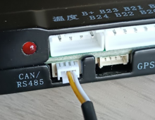
I have CAN port on JK-BMS

1714481601410.png

Can you tell me how to hook it up? have

1714481695950.png
and this
1714481710245.png

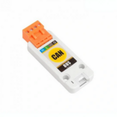
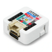
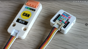
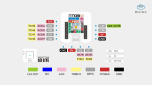
CAN-BUS comes with 4 pin cable so is it correct to connect CAN-BUS with esp32 ATOM with this calbe? Where connect my CAN from JK-BMS

1714481890680.png

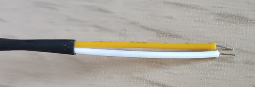
so where put cable from CAN port JK-BMS - its only two cable

1714482024566.png

my yaml is

Code:
# +--------------------------------------+
# | ESP32 CAN/serial port pins           |
# +--------------------------------------+
# GPIO pins your CAN bus transceiver ATOMIC CANBus Base (CA-IS3050G)
  can_tx_pin: GPIO5
  can_rx_pin: GPIO6
# GPIO pins your JK-BMS UART-TTL is connected to the grove port of Atom Lite
  tx_pin: GPIO1
  rx_pin: GPIO2

dont know it is correct according this
1714482138428.png

please let me know
 
Last edited:
Hello,

I have JK-BMS
View attachment 212413
its connected to Home Assistant VIA BT with esp32.
Can I have two esp32 devices connected to JK-BMS, one via BT and the other via cable with CAN at the same time?

I have CAN port on JK-BMS

View attachment 212414

Can you tell me how to hook it up? have

View attachment 212415
and this
View attachment 212416

CAN-BUS comes with 4 pin cable so is it correct to connect CAN-BUS with esp32 ATOM with this calbe? Where connect my CAN from JK-BMS

View attachment 212417

so where put cable from CAN port JK-BMS - its only two cable

View attachment 212418

my yaml is

Code:
# +--------------------------------------+
# | ESP32 CAN/serial port pins           |
# +--------------------------------------+
# GPIO pins your CAN bus transceiver ATOMIC CANBus Base (CA-IS3050G)
  can_tx_pin: GPIO5
  can_rx_pin: GPIO6
# GPIO pins your JK-BMS UART-TTL is connected to the grove port of Atom Lite
  tx_pin: GPIO1
  rx_pin: GPIO2

dont know it is correct according this
View attachment 212419

please let me know
I Think you would be interested in the TX/a Rx/b - so you want the Rx / Tx wire from the TTL of the GPS port

also i dont think CAN functions in the pasted version of the JKBMS - so you definitly must use the GPS port


Check out my link and vidoes:
 
  • Like
Reactions: knd
I Think you would be interested in the TX/a Rx/b - so you want the Rx / Tx wire from the TTL of the GPS port

also i dont think CAN functions in the pasted version of the JKBMS - so you definitly must use the GPS port
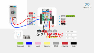
OK, so need connect GPS/485 from JK-BMS to ATOM S3 smth like this below?

jk-bms-inverter.jpg

so i need some cable GROVE with 4 pins to connect like this and two wire to connect esp32 to CAN-BUS?
 
can i use two esp32 simultaneously - one connected via BT (home assistant), second connected via wire to port CAN to inverter?

one is with

second is with
 
RS485 rtu slaves (BMS in this case) only reliably do comms with one master (ESP32), so expect gaps and freezes from time to time when 2 requests for data arrive at the BMS at the same time.

I have an SMA SI5048 RS485 slave feeding 2 RS485 masters, each polling every 15 secs, every 4 or 5 mins there is a glitch with wrong values and every 3 or so days the SI RS485 data chip freezes until I disconnect the 2 masters for 30 secs. If you can live with that then go ahead and try.
 
  • Like
Reactions: knd
Back
Top