cjdell
New Member
- Joined
- Aug 31, 2022
- Messages
- 17
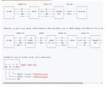
It's the full 52V on that pin. Be careful! If it accidentally touches the digital pins it'll surely fry something. I'm surprised they even made this decision to have a high voltage on such a tiny pin.Quick question,
What is the voltage on the vbatt pin on the rs485 connector?
I wonder can the esp32 be powered from it?
You could use a step down DC-to-DC converter from AliExpress or borrow a USB port from a nearby inverter or something.