We are currently attempting to extract CAN data from the CAN port of the JK BMS with Model No. JK_BD4A20S4P.
Did you explicitly order the CAN version? By default, CAN is not present; you have to select that you want CAN when buying.


We are currently attempting to extract CAN data from the CAN port of the JK BMS with Model No. JK_BD4A20S4P.
Hi,Hi uksa007...I have a JK BMS model B2A20S20P, I bought RS485 module and USB to RS485 to connect JK BMS to Raspberry/Solar Assistant.
I have Voltronic Inverter Max7200...can I connect my JK BMS to my inverter?
What I would like to understand...if I pay you $107 as requested..will I get everything needed (plug and play) to connect the JK BMS to my inverter? Sorry, just to understand..
Unless you specifically ordered the CAN version of the JK-BMS the CAN hardware is not present/enabled in the BMS.But still we are not getting any response from the BMS.
 github.com
Hi,Hi Uksa007. Im looking for plug and play solution. Is it possible to buy?
Im located in Ukraine so need to use dropshipping warehouse in US or EU country.
Inverter growatt spf 5000 esHi,
What make and model inverter and BMS do you have?
I can ship to any country 8-12 business day, often less.
Regards.
Great..keep me updated..I'm interested.Hi,
I'm currently working on an RS485 interface kit solution that would be plug and play, similar to my CAN version.
I'm waiting on some prototype boards to arrive.
The list I have suggests that Inverter supports CAN Bus.Inverter growatt spf 5000 es
So you can ship directly to Ukraine?
github.com
I did some testing with the Voltronic inverter a while ago, I think the only issue we had was there no way to control the discharge current in the inverter, it simply didn't support max discharge current even though we were sending it. The inverter itself doesn't have any register or ability to set it even manually.I have Voltronic Inverter Max7200...can I connect my JK BMS to my inverter?
Yes, I'm using CAN version BMS and CAN is also enabled from bluetooth applicationDid you explicitly order the CAN version? By default, CAN is not present; you have to select that you want CAN when buying.
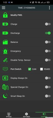
Hi..What version of the JK bms app is that?...it's the first time I've seen it with those options...I would appreciate it if you could tell me where I can download it...thanksYes, I'm using CAN version BMS and CAN is also enabled from bluetooth application
It just the latest version available from the normal app stores.Hi..What version of the JK bms app is that?...it's the first time I've seen it with those options...I would appreciate it if you could tell me where I can download it...thanks
Please let me know solution of this issueWe are currently attempting to extract CAN data from the CAN port of the JK BMS with Model No. JK_BD4A20S4P. We tried to use CAN Analyzer tool to understand the baud rate of the BMS as it mentioned in the support documentation that baud rate should be 250kbps.
View attachment 165645
However, we are not able to detect 250 kbps baud rate in our CAN analyzer tool.
View attachment 165646
We also tried to get the message from the BMS through our IoT device by setting its baud rate 250kbps. We given the request ID as per mention in below screenshot.
But still we are not getting any response from the BMS.
View attachment 165644
...............................
CAN type: Standard
CAN ID: 2F4
Data: 00 00 00 00 00 00 00 00
Thank you for your support, and we eagerly await your prompt response.
You are not using my code or hardware, there is no solution I can provide.Please let me know solution of this issue
OK, ThanksYou are not using my code or hardware, there is no solution I can provide.
I don't use the JK-BMS CAN interface, I use the RS485/GPS interface!
All I can suggest is that you test your CAN Analyzer tool with a known working CAN bus.
Make sure you have CAN H connected to CAN H, CAN L -> CAN L.
Make sure you have CAN bus terminated at both ends with 120 ohms, it should be 60 ohms with the bus connected at both ends.
Failing that I suggest you contact the seller and manufacturer of JK-BMS for support, maybe it is faulty or not the CAN model.
Regards
tried to connect with JK Team but didn't get any response.
Inverter support. Im not sure about BMS. Is it can version or rsThe list I have suggests that Inverter supports CAN Bus.
Can you confirm you can select battery communications type CAN L52(Pylon Protocol)?
If so you should be good.
I have sent several to Ukraine, I think it is taking longer than usual at the moment due to the war.
They are delivered by your local Ukrposhta
Current estimate is Standard 15-25 business days once shipped or Express (extra cost) 8-18 business days
More info here:

Hardware interface - now for sale · Uksa007 esphome-jk-bms-can · Discussion #16
Hi, This has all the hardware needed to communicate with BMS and Inverter over CAN bus. Hand built on a PCB and soldered to the ESP32, bulletproof design for production use. Don't use modules and D...
Inverter support. Im not sure about BMS. Is it can version or rs
github.com
I am currently using an isolated 48V => 5V DC-DC converter. Search for VRB4805S-6WR3 - This part works perfectly for me. I avoid non-isolated converters for this amount of drop-down, as a component failure (transistor or oscillator) will send full pack voltage to the ESP32, and potentially to the inverter. Isolated converters prevent this from happening.
Just note that the power supply must have low output ripple to avoid problems. RS485 would not read correctly due to high error rates with another converter I previously tried.


You should be fine with a common reference ground. The key reason for my selection of an isolated converter is mainly what happens in the rare event of oscillator failure. In 'cheap' non-isolated buck converters, an oscillator failure will cause input voltage to pass through the coil, causing Vout == Vin... likely causing major damage to everything directly (or indirectly) connected to the output. A fuse will not protect against this condition until it is already too late. In isolated converters, oscillator failure will cause a short on the input side of the transformer, which will blow the fuse - Vout will never exceed the rated output voltage.I used the URB4805YMD-10WR3 isolated 48V to 5V DC converter. The prototype works but only if I connect GND In with GND Out, if I don't connect the GNDs together I have a voltage difference of 30mv between the two GNDs and a lot of error with the JK BMS UART TTL input.
As a result I lose the isolation function of the DC-DC converter.
The card will be placed in the box with the battery. Only an RJ45 connector will be available on the front panel.
View attachment 167632