Maybe a super simple solution to this cold problem for people using NO relays controlled by their BMS (typically Chargery): just put the relays inside the insulated box containing your cells, this way the "wasted" energy used to keep the coils powered will be used to heat up the cells. Maybe that's enough to keep them warm?


You are using an out of date browser. It may not display this or other websites correctly.
You should upgrade or use an alternative browser.
You should upgrade or use an alternative browser.
LiFePO4 heating pad for cold temperatures
- Thread starter Will Prowse
- Start date
grizzzman
Photon Vampire
- Joined
- Sep 21, 2019
- Messages
- 2,768
Maybe a super simple solution to this cold problem for people using NO relays controlled by their BMS (typically Chargery): just put the relays inside the insulated box containing your cells, this way the "wasted" energy used to keep the coils powered will be used to heat up the cells. Maybe that's enough to keep them warm?
Then move them in the hot summer? Seems not simple?
FilterGuy
Solar Engineering Consultant - EG4 and Consumers
I like the thinking, but if you have a well insulated box and an always on heat source, you could drive the temp too high....Maybe a super simple solution to this cold problem for people using NO relays controlled by their BMS (typically Chargery): just put the relays inside the insulated box containing your cells, this way the "wasted" energy used to keep the coils powered will be used to heat up the cells. Maybe that's enough to keep them warm?
Edited with more info on insulation.
A while back I did some thermal dynamic calculations and determined that 10whrs/day would hold the temp in an R30 insulated box if the temp outside the box was 20deg C lower. The relays will be driving 15 or 20 times that.
The box is going to have to be opened up in the summer no matter what, so that does not seem like a problem. The problem is that they are an unregulated heat source.Then move them in the hot summer? Seems not simple?
Last edited:
Alright, then you can think about a tunable heat exchanger that could be setup across the insulated box wall: for instance an aluminium radiator with a fan attached. When the fan doesn't blow the heat flow from the box is not so fast (thermal resistance increased), but when it blows on the radiator the heat from inside the box is dissipated faster.I like the thinking, but if you have a well insulated box and an always on heat source, you could drive the temp too high....
Edited with more info on insulation.
A while back I did some thermal dynamic calculations and determined that 10whrs/day would hold the temp in an R30 insulated box if the temp outside the box was 20deg C lower. The relays will be driving 15 or 20 times that.
The box is going to have to be opened up in the summer no matter what, so that does not seem like a problem. The problem is that they are an unregulated heat source.
But that starts to be a complicated system for a simple task ^^ or you could adjust the insulation of you box according to the season (with adjustable vents) to keep your battery in the right range of temperature. Might even be automatized with some step motors and an Arduino if more precise regulation is needed.
Just trying to find some use for waste energy here, but of course for those who don't care about efficiency a resistive heatpad would be simpler and more fail proof.
The pads may fail to do their job. They might break down or just become to weak to heat up the battery in a manner they should do. They might also have not enough power to warm up in very cold situations. What will you do then? If you don't realize the problem fast enough, this might destroy your cells irreversibly. So I'd like to have a relay installed as a fallback solution.
I'm not sure, but doesn't a normally closed nc-relay consume power only to keep it open? So it would just need energy if it gets its signal, which means only during the time, the pads are heating. Which would on the other hand mean - coming to the solution I prefer - the heating pads and the relay would only need power when an attached charger is going to charge the battery, otherwise they won't consume anything.
I'm not sure, but doesn't a normally closed nc-relay consume power only to keep it open? So it would just need energy if it gets its signal, which means only during the time, the pads are heating. Which would on the other hand mean - coming to the solution I prefer - the heating pads and the relay would only need power when an attached charger is going to charge the battery, otherwise they won't consume anything.
Last edited:
FilterGuy
Solar Engineering Consultant - EG4 and Consumers
The pads may fail to do their job. They might break down or just become to weak to heat up the battery in a manner they should do. They might also have not enough power to warm up in very cold situations. What will you to then? If you don't realize the problem very fast, this might destroy your cells irreversible.
Heat-Pad failures:
I can't say I have any experience in heat pad failures, but they are pretty darn simple devices. I would think a failure of the heating element would be pretty unlikely. If the element does fail, the most likely failure mode would be an open circuit (no heat). I would be more worried about the thermostat failing, but even that is unlikely. If the thermostat fails open, you get no heat. The bigger failure would be if the thermostat sticks 'on'. In this case you could quickly cook your batteries if they are in a well insulated box (This is a good reason not to use any higher wattage than you need.). I generally don't like adding components, but one way to deal with the 'stuck on' failure is to add a second thermostat in series.
Cold creates two problems:
1) You can't charge below ~0C (preferably don't charge below ~2C)
You should always have a low-temp charge cut-off if there is any chance of getting this cold. This can be done in many ways. Some chargers have the capability. A lot of BMSs have the capability. There are external circuits that can do it. Therefor the worst case scenario for a heat pad not working is that the low-temp cut-off kicks in. and you can't charge. While this may be inconvenient, it may be the best solution. Depending on your situation, adding complexity to heat things up may not be worth the gains. (Example, if you are in an RV and the battery is in the living space, you will have other ways of heating the living space if it gets that cold)
2) Cold storage or usage below about -20C gets iffy.
A lot of installations will never see this kind of cold....
Some BMS's have a cold discharge cut-off. If you have one of those, you are really only talking about a problem of storage at that temp.
I would venture to say that for a lot of the installations that might see -20C, a well insulated box will be all it takes to ride out the cold snap.
If you are in a situation where you might not be able to ride out the cold snap, a small heat-pad in a well insulated box might be appropriate.
Note: One way to reduce the risk of cold storage problems is to place two of these in the box. If the temp gets down to the freezer block freezing point, the phase-change energy release will hold the temp at the freezing point for a long time. (I calculated that in an R30 insulated box, two of these could keep the temp constant for 3 or 4 days if the outside temp is 20C below the freeze temp of the block.)
Yes, a failure could be an inside broken pad, once heating it too long, this might happen. But normally it doesn't if the selected material isn't planned to weak. (planned obsolescence?)
When it comes to the pads I'd like to have, overheating should no be a problem, even without a thermal control. According to the seller, the highest possible temperature they can make is about 60°C. In this area even the BMS does not cut off.
The wattage is 3x12W. I'm not sure about it, but my insulation is very limited. The battery has maximum dimensions it must not exceed. It well be a 400Ah with 8x aluminium cells packed into a case about W340 x L365 x H205 mm. I don't think this is oversized, but we'll see, if it doesn't match there still can be attached more of them or removed.
When it comes to charging below freeze, external solution are no option to me. It has to be solved by the battery itself. Of course, having a BMS doing the job, I would not need a relay. But I don't... . But I agree, a BMS with low-temp cut off is one of the best solution you can have for this job.
In my opinion the most dangerous temperature is somewhere between -10 - 0°C. The battery might see this temperatures very fast and not so rare during a normal winter if your car is not used just for a few hours and not becoming warmed up by e.g. a heated garage or an installed parking heater in the car.
Hmm, the freezer packs are a nice idea, but I'like to have something more controllable that may last longer. I also think of situations where the car will stay untouched for days or even weeks in the coldness. The battery should be able to handle it without me worrying the whole time about it.
Asking the other way round, what speaks against installing a relay, are there any reasons why one should not do it? Ok, it makes the installation more complex. In my case I'm going to take the risk, what else?
When it comes to the pads I'd like to have, overheating should no be a problem, even without a thermal control. According to the seller, the highest possible temperature they can make is about 60°C. In this area even the BMS does not cut off.
The wattage is 3x12W. I'm not sure about it, but my insulation is very limited. The battery has maximum dimensions it must not exceed. It well be a 400Ah with 8x aluminium cells packed into a case about W340 x L365 x H205 mm. I don't think this is oversized, but we'll see, if it doesn't match there still can be attached more of them or removed.
When it comes to charging below freeze, external solution are no option to me. It has to be solved by the battery itself. Of course, having a BMS doing the job, I would not need a relay. But I don't...
. But I agree, a BMS with low-temp cut off is one of the best solution you can have for this job.In my opinion the most dangerous temperature is somewhere between -10 - 0°C. The battery might see this temperatures very fast and not so rare during a normal winter if your car is not used just for a few hours and not becoming warmed up by e.g. a heated garage or an installed parking heater in the car.
Hmm, the freezer packs are a nice idea, but I'like to have something more controllable that may last longer. I also think of situations where the car will stay untouched for days or even weeks in the coldness. The battery should be able to handle it without me worrying the whole time about it.
Asking the other way round, what speaks against installing a relay, are there any reasons why one should not do it? Ok, it makes the installation more complex. In my case I'm going to take the risk, what else?
FilterGuy
Solar Engineering Consultant - EG4 and Consumers
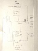
I am not clear on where the relay would be. Could you tell me more on "installing a relay"? Perhaps a diagram?Asking the other way round, what speaks against installing a relay, are there any reasons why one should not do it? Ok, it makes the installation more complex. In my case I'm going to take the risk, what else?
This is just a first try I made on paper to make it faster.
Some final decisions are not made jet, e.g. the main switch could become rationalized and exchanged by a smaller one just switching the signal for the relay. By now I also don't know if it's not better to contact the power supplies (+ & -) for the controllers and the pads directly to the battery instead of the poles. But I'd like at least the voltage-controller to have the charging voltage coming through the poles as fast as possible. It may also be a better idea to put the minus of the controllers and pads between the BMS and the battery minus, so that the supply would stay connected even when the BMS cuts off and no charging current is applied. Also the plus may change its position between the relay and battery. I must think about the consequences doing so. As you see, there is still much to do about it, but I think, the idea behind should be clear?
Some final decisions are not made jet, e.g. the main switch could become rationalized and exchanged by a smaller one just switching the signal for the relay. By now I also don't know if it's not better to contact the power supplies (+ & -) for the controllers and the pads directly to the battery instead of the poles. But I'd like at least the voltage-controller to have the charging voltage coming through the poles as fast as possible. It may also be a better idea to put the minus of the controllers and pads between the BMS and the battery minus, so that the supply would stay connected even when the BMS cuts off and no charging current is applied. Also the plus may change its position between the relay and battery. I must think about the consequences doing so. As you see, there is still much to do about it, but I think, the idea behind should be clear?
Attachments
FilterGuy
Solar Engineering Consultant - EG4 and Consumers
Is this an acurate re-draw of your idea? (I assume the heat pads have a built in thermostat)This is just a first try I made on paper to make it faster.
Some final decisions are not made jet, e.g. the main switch could become rationalized and exchanged by a smaller one just switching the signal for the relay. By now I also don't know if it's not better to contact the power supplies (+ & -) for the controllers and the pads directly to the battery instead of the poles. But I'd like at least the voltage-controller to have the charging voltage coming through the poles as fast as possible. It may also be a better idea to put the minus of the controllers and pads between the BMS and the battery minus, so that the supply would stay connected even when the BMS cuts off and no charging current is applied. Also the plus may change its position between the relay and battery. I must think about the consequences doing so. As you see, there is still much to do about it, but I think, the idea behind should be clear?

I think it is what is in the drawing but I can't reconcile that to what you describe. (Particularly the voltage controller). Is the voltage controller your solar charge controller? Are you trying to rout the charge current to the heat pads instead of the battery when the temp controller decides the heat pads should be on? (I don't think the drawing does this)
Here is a drawing for what I *think* is being attempted:
(I am assuming the heat pads have a built in thermostat)

Note that I added the flyback diode.
Getting a 2PDT contactor that would handle the current will be a bit of a challenge but they do exist, (Search for DC contactors with auxilary). You might have to use two relays (The relay for the charge current could be smaller)

Warning: Some charge controllers don't like to be hooked/unhooked from the load while the charge source is energized. I don't know if the short moment the relay is switching will hurt.... but be aware.
What I see in this is too much complexity. If I I had no other choice, I guess I would consider something like this, but frankly, I would work hard to avoid adding all of this to the system if I could. (Even if it means I can't charge in the morning sometimes) Adding all of this also adds more points of failure.
Someone earlier suggested using a low watt 120V heat pad and plug it into the inverter. That is what I would do if I really felt I needed a heat pad on an active system. However, everyone has different circumstances and different approaches. All I can offer is my opinion.
I see, I have to start a bit earlier. In this post I described all used components and linked to them: https://diysolarforum.com/threads/lifepo4-heating-pad-for-cold-temperatures.5/post-32925
The pads does not have their own temperatur control. The two controllers are meant to handle this.
The two controllers are only modules. The temperatur controller works like a thermostat. When the temperature drops below a certain point it passes a load signal. This signal will energize the voltage-controller. It's mission is to pass a load signal, when the voltage rises into the areas of charge voltage. It detects charge voltage.
Doing so now I have a load-signal that depends on temperatur and voltage. Because the two controllers can manage up to 10A I can use this signal line to power the heating pads. They will heat as long as either the temperature rises beyond a certain point or the voltage drops below charging voltage. So these two controllers decide when to heat and when not.
Additionally I'd like to have this signal to also manage the nc-relay. The normally closed relay will open to cut off the plus line between battery-cells and battery-poles.
So yes, I'm trying to pass the charge current through the temp-controller, then through the voltage-controller and from there on to the pads and also the relay-steering.
Everything I've sketched above is meant to happen inside a battery-case and will be part of the battery. I want to be able to attach any kind of chargers to the battery and it will protect the same way.
Hmm, I'd like to know how the builders of the BMSes with integrated low temp cut off have solved this problem.
Your first drawing differs from mine in two points:
1) You connected the voltage-controller first and than attached the temperature controller. So it's now dependent on it, I did it the other way round.
2) The two controllers in your drawing are powered only by the battery. In mine they are powered by both, battery and charger, depending on the switching position of the relay. (If relay is closed and there is no charge current, it's powered by the battery, otherwise it's powered by the charge current because the relay only opens when a charge current is available through the battery poles.)
I also abstracted the cell managing/balancing lines coming from the BMS because for me they are not important here.
When it comes to drawing 2 and 3. The charge current comes from outside the battery directly through the battery poles, not over a separate line. I am also going to pass the charge current through the controllers, so there is absolutely no need for a 2PDT to do so. That's because the controllers can pass up to 10A and they by themselves act like a relay.
In my drawing in fact there are two plus-lines going to the temp-controller, one is to feed the controller itself with power and the other one is the actual signal-line that will be passed to the voltage-controller and used later for the heating pads. I just abstracted this in the drawing, because I'll bypass the line near the controller itself. But I've seen, you'd been drawing this.
The whole thing is very simple but I'm not a native english speaking person so it's a little bit hard to explain. Especially the controller-modules make the things very easy.
P.S. When it comes to complexity of electronic components, you're right, the two controllers have additional components that may fail. But, on the other hand, the more complex your BMS gets (and it does with all the protection systems onboard), the more electronic components can also fail inside your BMS. Here I'm balancing a simpler BMS with additional controller-modules.
The pads does not have their own temperatur control. The two controllers are meant to handle this.
The two controllers are only modules. The temperatur controller works like a thermostat. When the temperature drops below a certain point it passes a load signal. This signal will energize the voltage-controller. It's mission is to pass a load signal, when the voltage rises into the areas of charge voltage. It detects charge voltage.
Doing so now I have a load-signal that depends on temperatur and voltage. Because the two controllers can manage up to 10A I can use this signal line to power the heating pads. They will heat as long as either the temperature rises beyond a certain point or the voltage drops below charging voltage. So these two controllers decide when to heat and when not.
Additionally I'd like to have this signal to also manage the nc-relay. The normally closed relay will open to cut off the plus line between battery-cells and battery-poles.
So yes, I'm trying to pass the charge current through the temp-controller, then through the voltage-controller and from there on to the pads and also the relay-steering.
Everything I've sketched above is meant to happen inside a battery-case and will be part of the battery. I want to be able to attach any kind of chargers to the battery and it will protect the same way.
Warning: Some charge controllers don't like to be hooked/unhooked from the load while the charge source is energized.
Hmm, I'd like to know how the builders of the BMSes with integrated low temp cut off have solved this problem.
Your first drawing differs from mine in two points:
1) You connected the voltage-controller first and than attached the temperature controller. So it's now dependent on it, I did it the other way round.
2) The two controllers in your drawing are powered only by the battery. In mine they are powered by both, battery and charger, depending on the switching position of the relay. (If relay is closed and there is no charge current, it's powered by the battery, otherwise it's powered by the charge current because the relay only opens when a charge current is available through the battery poles.)
I also abstracted the cell managing/balancing lines coming from the BMS because for me they are not important here.
When it comes to drawing 2 and 3. The charge current comes from outside the battery directly through the battery poles, not over a separate line. I am also going to pass the charge current through the controllers, so there is absolutely no need for a 2PDT to do so. That's because the controllers can pass up to 10A and they by themselves act like a relay.
In my drawing in fact there are two plus-lines going to the temp-controller, one is to feed the controller itself with power and the other one is the actual signal-line that will be passed to the voltage-controller and used later for the heating pads. I just abstracted this in the drawing, because I'll bypass the line near the controller itself. But I've seen, you'd been drawing this.
The whole thing is very simple but I'm not a native english speaking person so it's a little bit hard to explain. Especially the controller-modules make the things very easy.
P.S. When it comes to complexity of electronic components, you're right, the two controllers have additional components that may fail. But, on the other hand, the more complex your BMS gets (and it does with all the protection systems onboard), the more electronic components can also fail inside your BMS. Here I'm balancing a simpler BMS with additional controller-modules.
Last edited:
FilterGuy
Solar Engineering Consultant - EG4 and Consumers
Is this what you have in mind?

Edited to clarify circuit.
Edited to clarify circuit.
When it comes to power consumption I made some scenarios with data I got from the informations found around the components itself. These are NOT results of measurements. All these scenarios are meant according to the described wiring diagram.
TEMP beyond freeze | no charge current | powered by battery
Temp-Controller: 30-40mA
Voltage-Controller: 0 mA
Heating-Pads: 0A
Relay : 0A (its normally closed, not sure here)
TEMP beyond freeze | charge current | powered by charger
Same as above
TEMP below freeze | no charge current | powered by battery
Temp-Controller: 60-70mA
Voltage-Controller: 10 mA
Heating-Pads: 0A
Relay : 0A (its normally closed, not sure here)
TEMP below freeze | charge current | powered by charger
Temp-Controller: 60-70mA
Voltage-Controller: 10 mA
Heating-Pads: 3A
Relay : 0,3-1A
Components:
Temp-Controller: https://de.aliexpress.com/item/33042545471.html
Voltage-Controller: https://de.aliexpress.com/item/32996091128.html
Heating-Pads: https://de.aliexpress.com/item/4000448687939.html
Relay : [still searching, but what I've found should make around these Amps]
FilterGuy
Solar Engineering Consultant - EG4 and Consumers
OK.... I m still missing something..... the relay in my drawing must be wired different than you expected.
Is this what you have in mind?
Yes, that looks much better, I just want to have the power-line which is going to the temp-controller attached next to the battery-poles. In your drawing it would be the plus very right of the relay and the main switch. This will force to power the temp-controller by the charger when the relay is open. It will also disable the whole protection when the battery is cut off by the main switch and so the temp-controller display. Looking at the diagram posted the whole protection would be charged by the battery when the relay is opened.
Last edited:
FilterGuy
Solar Engineering Consultant - EG4 and Consumers
Is this it?

I think I am understanding now. (Sorry it took so long)
The logic all seems to work.....but is sure seems complicated
Does your BMS have low voltage cut-off and low temp cut-off?
I think I am understanding now. (Sorry it took so long)
The logic all seems to work.....but is sure seems complicated
Does your BMS have low voltage cut-off and low temp cut-off?
Yeah, this looks fine.
It' s one of the better known Daly's (12V 4S 200A common port) https://de.aliexpress.com/item/32921950553.html.
It should have high/low voltage cut-off and high temp cut off. But looks like it is missing the low temp cut-off.
Does your BMS have low voltage cut-off and low temp cut-off?
It' s one of the better known Daly's (12V 4S 200A common port) https://de.aliexpress.com/item/32921950553.html.
It should have high/low voltage cut-off and high temp cut off. But looks like it is missing the low temp cut-off.
Last edited:
FilterGuy
Solar Engineering Consultant - EG4 and Consumers
OK that makes sense to me now. You have to have the temp cut-off circuit anyway so you might as well add the heater.
I'd understand that the targets should be to heat up the air inside the batt' box above freezing which would affect the object temperature of the battery cells. In this case it wouldn't matter what the object heat of the heater pad is, correct? The heater control system would shut off the pads above freezing temperature inside the box.My install is for a 5th wheel so will only activate it when it's cold/freezing out in the desert areas. It's also way gentler on the batteries than the silicon heating pads that go up to 80deg C. (180+ Fahrenheit ! which is way too high for LFP) I'll be able to monitor the bat temp with my BMV-712 so it will be an easy manner to determine a good setting of 40-50deg F. anything above 35 or 40 should be good for charging during cold days. I've ordered two so will let everyone know how they work out.
Similar threads
- Replies
- 2
- Views
- 591
- Replies
- 8
- Views
- 440