diy solar

diy solar

Load sharing between 2 inverters in split phase config.

I assume your talking about one like this and you’re right, they are all over eBay: https://www.ebay.com/itm/3838823988...624&ssuid=&var=&widget_ver=artemis&media=COPY

While that will work, 240V in and 120/240V out so it distributes load evenly across the two inverters, any of these transformers is far from "ideal". They are optimized for cost, while carrying a tolerable no-load current. Your inverter may or may not be happy with that (more battery drain, and a few amps out of phase current to source and then sink, an "inductive" load.) Note the current waveform that is not a sine wave, more like a Hershey's kiss. And 7x greater than in my previous posting:


What you want is closer to an ideal transformer/inductor, with low sine-wave current draw. I get decent behavior when I drive a 240V coil with 120V, vs. driving with 240V. I can use an oversized transformer and two 240V primary windings as a 120/240V auto-transformer, but I haven't seen any I can use as 240V to 120/240V isolation transformer while operating the windings at 1/2 of rated voltage. I could do it with two transformers.

Do you have a signal available that indicates grid connected/not connected? If so, you could use an auto-transformer to partially rebalance load on the inverters only when off-grid. It would be disconnected when on grid.
 
I too have pair of 3K inverters. Whenever one of mine sees a peak in excess of its capacity, I see a bit of grid assist for the duration of the peak.
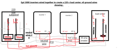
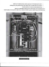
I am in the process of combining two EG4 3000 inverters to make split phase, because i added a 220v mini split heat/Ac unit. Is there a method to wire them, that would minimize the balancing problem ? I thought that if you keep the L1 and L2 on the same source , it would help . this funky diagram shows what I intend t0 do. ii see this other pic from Will that shows the supply breakers on one leg and the loads on the other. let me know if you have any opinion of my drawing or Will's.
 

Attachments

  • wiring4split phaae.png
    wiring4split phaae.png
    98 KB · Views: 8
  • Document_2023-04-01_055305.jpg
    Document_2023-04-01_055305.jpg
    158.4 KB · Views: 9
I am in the process of combining two EG4 3000 inverters to make split phase, because i added a 220v mini split heat/Ac unit. Is there a method to wire them, that would minimize the balancing problem ? I thought that if you keep the L1 and L2 on the same source , it would help . this funky diagram shows what I intend t0 do. ii see this other pic from Will that shows the supply breakers on one leg and the loads on the other. let me know if you have any opinion of my drawing or Will's.
Main panel double pole 30 amp breaker > inverters in > inverters out > double pole 30 amp breaker > manual transfer switch (where I have already brought 10 circuits out of the main panel.
This is a 240 volt split phase manual transfer switch.

I am no longer using the 30 amp twist lock receptacle. I disconnected it and ran the inverter output through a standalone double pole 30 amp into that Port of the manual transfer switch.
 
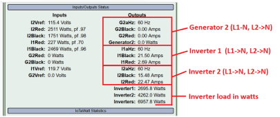
I run 2 x 12,000w inverters that are just 'plain' inverters and not stackable or parallelable. This means that each 120v leg of each inverter maxes out at 6000w. So.... I went to a reasonable amount of trouble (but not that much trouble) to feed the 120v home circuits in a balanced way so that if everything in the house is turned on at the same time, no single 120v set of circuits goes over the 6000w. Here's an example of a typical load distribution among the inverters.
1680461302316.png

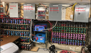
By using inverter distribution boxes + monitoring, over time, I become more familiar with home use patterns and it wasn't that hard to move breakers in the inverter distribution boxes from one 120v leg to the other and achieve balance + all can be on at the same time. Here's a visual of the inverters -> distribution boxes.
1680461172013.png
 
Last edited:
So i have 2x EG4 3000EHV-48, wired in a split phase (220v [L1-110v/N/L2-110v]) config into an Critical loads panel.
what did you end up doing ? Ihave the same system. mine stay pretty closely balanced by accident , I guess. I am thinking about a larger inverter because me and my three renters came close to maxing them out when it got over100 degrees all July .
 
what did you end up doing ? Ihave the same system. mine stay pretty closely balanced by accident , I guess. I am thinking about a larger inverter because me and my three renters came close to maxing them out when it got over100 degrees all July .
well went the easy way and just balanced the load circuits manually. DID try an auto transformer , but that made no diff. for now one leg gets 100W more than the other , which is ok and lets face it can never be truly balanced. and even in load with everything running they are 300w offset.. I am NOT running my AC/Dryer on this yet.
 
mine are sometimes 700 watts different with no problems. I run a 110v dryer and two Mini splits AC, and sometimes two more window Ac's at the same time. The only reason that I went to split phase was for the 220V mini splts, and i'm putting in a third one this month to replace a window AC. the mini splits startup at 700 watts and after fifteen minutes, run at 400 watts. And they don't burn any gas on heat mode. I don't see how you can un balance a 220v breaker, since it uses one leg from each invertor, and how do they decide which inverter to read on?
 
Last edited:
Back
Top