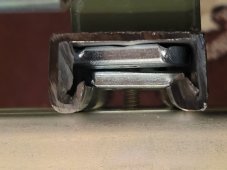
Pillow bearings are definitely “overbuilt” but I had a hard time finding anything else that was similar but not “overbuilt” either it just wouldn’t work or way over complicated or needed custom machined pieces. The other options I found were pre made solutions from solar companies. Anything with “solar” in the title seems to carry a high premium too, no matter how basic it is so that was put in principle alone. Pillow bearings are simple, budget friendly, and they work. I got this from a guy on eBay. He designed and builds them. It works well but doesn’t have the lcd screen and bells and whistles. It works great though.


")