I'd like to put in a manual transfer switch, something like the Yeti Home Integration Kit. I'd like to have the choice of using power station (probably Bluetti) or generator as power source. Does the Yeti only work with their power stations? Is there a recommended manual switch? TIA.


You are using an out of date browser. It may not display this or other websites correctly.
You should upgrade or use an alternative browser.
You should upgrade or use an alternative browser.
Manual Transfer Switch
- Thread starter dmholmes
- Start date
svetz
Works in theory! Practice? That's something else
Not a hardware guy, but if you Google "Circuit Transfer Switch" or "generator transfer kit", there will be a lot varieties, features, and prices. You can get them from Lowes or HomeDepot too... although generator stores might have them for less...
efficientPV
Solar Addict
- Joined
- Sep 24, 2019
- Messages
- 1,351
HERE IS A WARNING. I wanted to do some other manual switching of sources. I bought a QS-60 60A 380V 3 phase motor reversing switch, ON - OFF ON. If the jumpers are removed it is two contacts closed in one direction and two other in the other direction. It should have a very nice center off position where nothing is on. But, in China they do everything to save a little plastic on the cam. For a very short section of the lever movement both switches can be on at the same time shorting everything out. Switch went up in flames. I couldn't believe it, but I was able to reproduce it on the bench. Don't just buy anything for a transfer switch or you may blow something else up.
HERE IS A WARNING. I wanted to do some other manual switching of sources. I bought a QS-60 60A 380V 3 phase motor reversing switch, ON - OFF ON. If the jumpers are removed it is two contacts closed in one direction and two other in the other direction. It should have a very nice center off position where nothing is on. But, in China they do everything to save a little plastic on the cam. For a very short section of the lever movement both switches can be on at the same time shorting everything out. Switch went up in flames. I couldn't believe it, but I was able to reproduce it on the bench. Don't just buy anything for a transfer switch or you may blow something else up.
Thanks for the heads up. I'm looking at a ProTran2 switch like GZ uses. I'll run it by the electrician that will install the switch.
Hedges
I See Electromagnetic Fields!
- Joined
- Mar 28, 2020
- Messages
- 20,670
I'd like to put in a manual transfer switch, something like the Yeti Home Integration Kit. I'd like to have the choice of using power station (probably Bluetti) or generator as power source. Does the Yeti only work with their power stations? Is there a recommended manual switch? TIA.
Portable Power Stations, Solar Generators & Home Backup | Goal Zero
Experience the power of Goal Zero by improving your lifestyle with our portable power stations, solar generators, solar panels, power banks, and home energy storage solutions.
 www.goalzero.com
That's a typical transfer switch, will work with anything that has a 3-prong cord matching the recessed plug. With its several breakers and wires, it can draw power from one breaker in the utility panel and drive several house circuits (disconnected from their original breaker and connected by wire nuts to this unit.)
Simplest and cheapest "transfer switch" is to unplug an appliance and plug it into your inverter.
Another UL listed solution is an interlock on the cover of your breaker panel, which mechanically blocks the lever of the main breaker so you can throw another one as backfeed. You just need to turn off circuits you're not trying to power like your electric range.
Generator interlock kit Square D Homeline 100 Amp Panels | GenInterlock
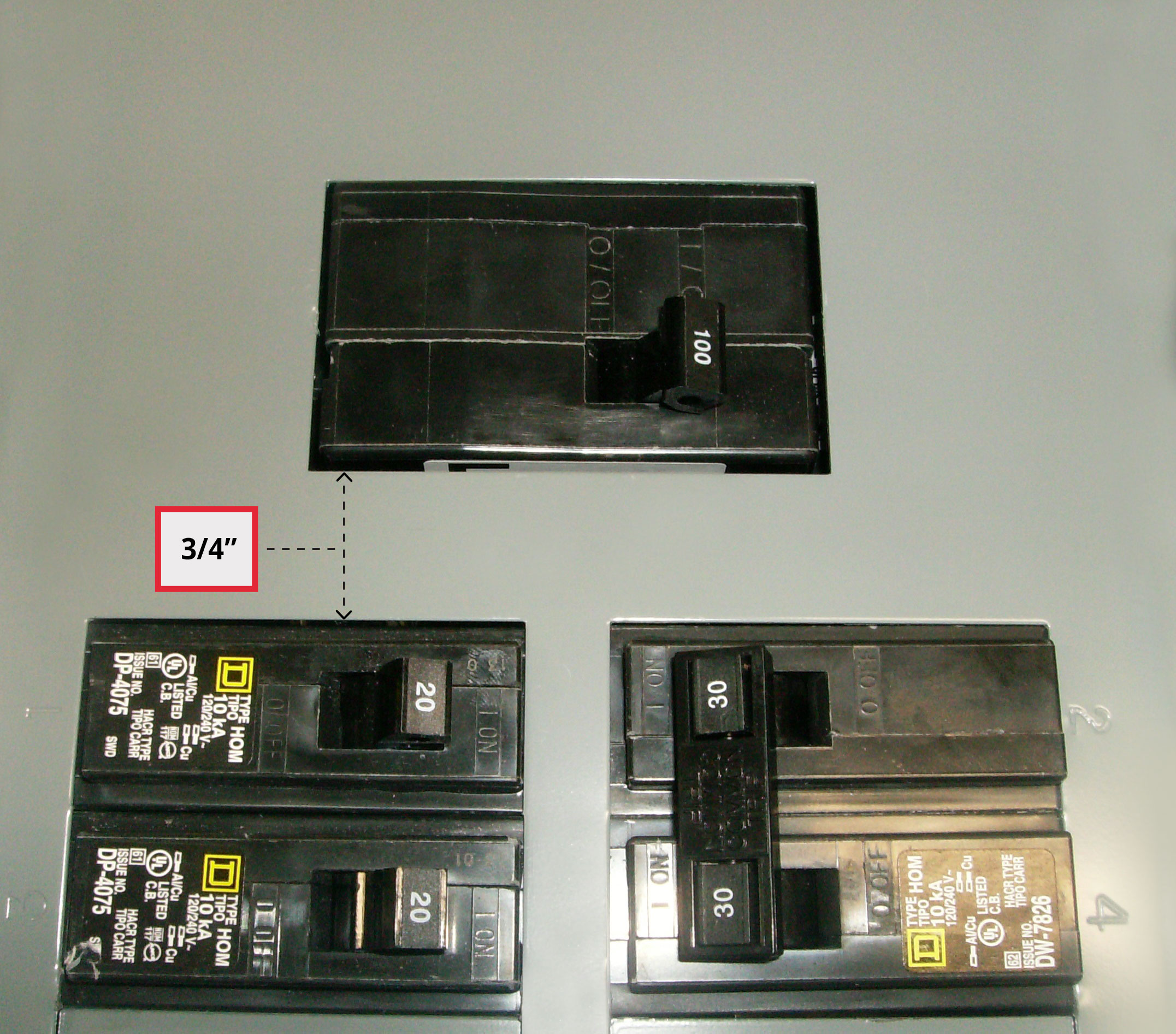
Main Breaker: 100 amp single handle Horizontal throw Right (on) and left (off) 3/4 Spacing between main and first row of breakers Generator Breaker: Top right side 2 positions
 www.geninterlock.com
Simplest and cheapest "transfer switch" is to unplug an appliance and plug it into your inverter.
Yep, that's what I'm trying to replace
")
Rider
Solar Addict
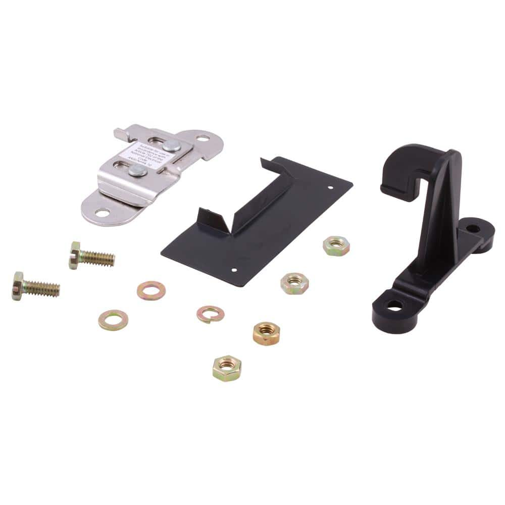
When I replaced my breaker panel, I had the electrician install one of these and a 30A outdoor jack for the generator. Simple, not expensive (for the interlock, the install of the external wire and jack was about $500). For the number of times I would ever use the interlock, it was a better solution than a full-on manual transfer switch.Another UL listed solution is an interlock on the cover of your breaker panel, which mechanically blocks the lever of the main breaker so you can throw another one as backfeed. You just need to turn off circuits you're not trying to power like your electric range.
When I replaced my breaker panel, I had the electrician install one of these and a 30A outdoor jack for the generator. Simple, not expensive (for the interlock, the install of the external wire and jack was about $500). For the number of times I would ever use the interlock, it was a better solution than a full-on manual transfer switch.
That sounds like a nice option. Our breaker has more than 1 switch on the main. Can an interlock work with that?

Rider
Solar Addict
Have to admit, that's the first dual-main breaker I've seen. IF the dual-main breakers are independent circuits, the left feeding the left row of breakers, and the right feeding the right row, it might be possible, but the spacing between the line and the main breaker is more than my interlock could span.
I'd confer with an electrician. He may have an option.
I'd confer with an electrician. He may have an option.
Rider
Solar Addict
This is the interlock on my panel. You can see how it blocks either the main or genny breaker from being engaged.

This is the interlock on my panel. You can see how it blocks either the main or genny breaker from being engaged.
View attachment 18639
Thanks, very nice. I did watch a few videos on it, looks like a better option than the transfer switch in a most cases.
GE PowerMark Gold Load Center/Generator Interlock Kit THQLLX1 - The Home Depot
There's no need for a separate generator panel with the GE PowerMark Gold Load Center/Generator Interlock Kit. This kit includes everything required to change a 150 - 225 Amp load center to a generator
www.homedepot.com
This matches my breaker panel by name, but as you can see from the photo at the bottom it clearly wouldn't work. Since my panel has the main switch going up and down while the circuit switches go left/right I don't think there could possibly be an interlock that would work. So the next question is would it be better to replace the breaker panel and do an interlock or go with the transfer switch?
Deleted-User
New Member
- Joined
- Oct 18, 2019
- Messages
- 144
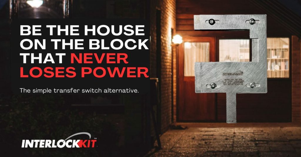
Interlock Kit & Accessories For Your Home | Generator Interlock Kit
Our Interlock Kits act like manual transfer switches for electrical panels providing safe, easy connections between homes & portable generators.
 www.interlockkit.com
Has these for a whole host of different brands and configs.
Hedges
I See Electromagnetic Fields!
- Joined
- Mar 28, 2020
- Messages
- 20,670
That sounds like a nice option. Our breaker has more than 1 switch on the main. Can an interlock work with that?
Google is your friend (and your spy)
I think I found it:
" GE-200HDA GE Generator Interlock for Verticle Main 150 or 200 amp "
generator Interlock kit | Https://www.ufindwhat.com/
Generator to home connections can be safely done. With an interlock kit specific to your panel. Find your kit here
 www.ufindwhat.com

GE-200HDA General Electric Generator interlock kit 150 200 Amp Panels LISTED | eBay
Find many great new & used options and get the best deals for GE-200HDA General Electric Generator interlock kit 150 200 Amp Panels LISTED at the best online prices at eBay! Free shipping for many products!
www.ebay.com
As you just found, the name matched some for panels with other orientation main breakers, but I think I found the one you need.
https://www.bluesea.com/products/category/7/38/Switches/Rotary_Switches Used many of these in generator set-ups.
I am about ready to have the interlock and inlet outlet installed. This is for use with a Honda EU2200i generator, Giandel 1200W inverter, and/or MPP Solar 1200LV-MS.
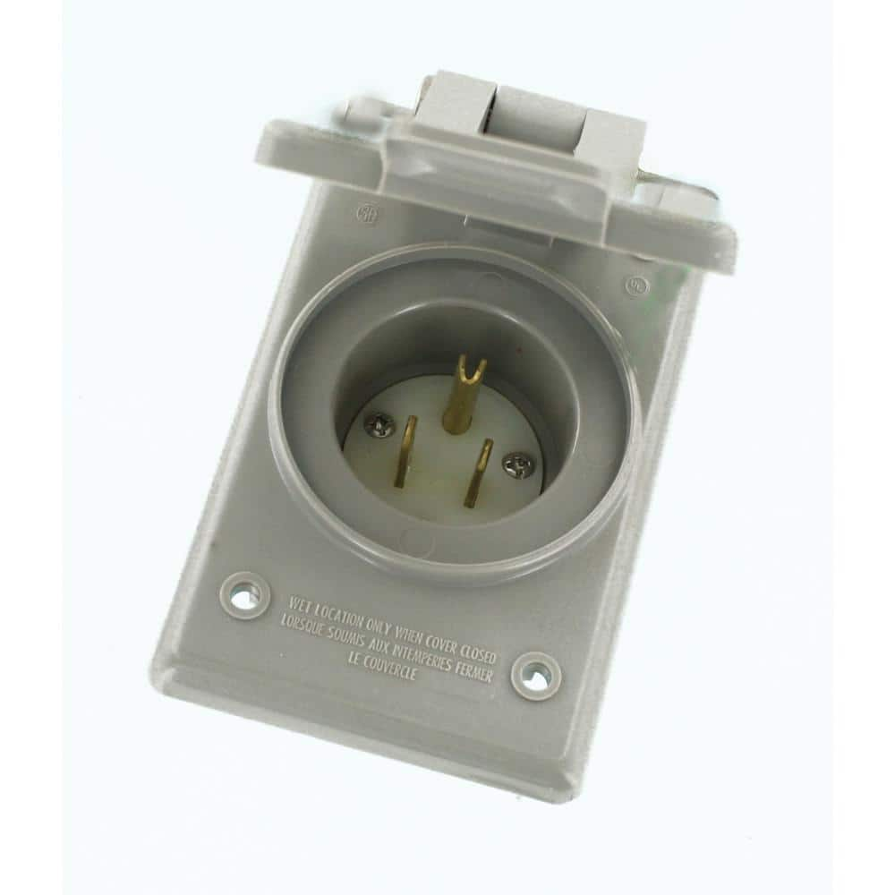
I was planning on going with this 15 amp inlet:
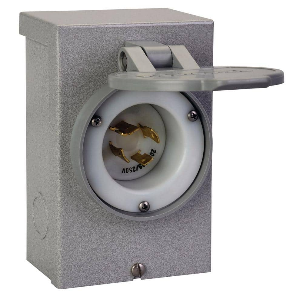
But I'm thinking about future-proofing with a 20 or 30 amp inlet.
20A:
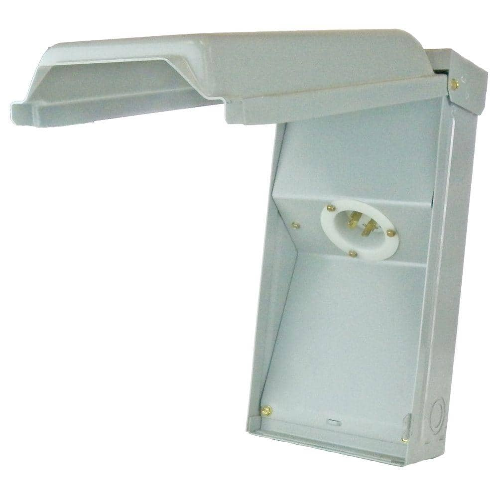
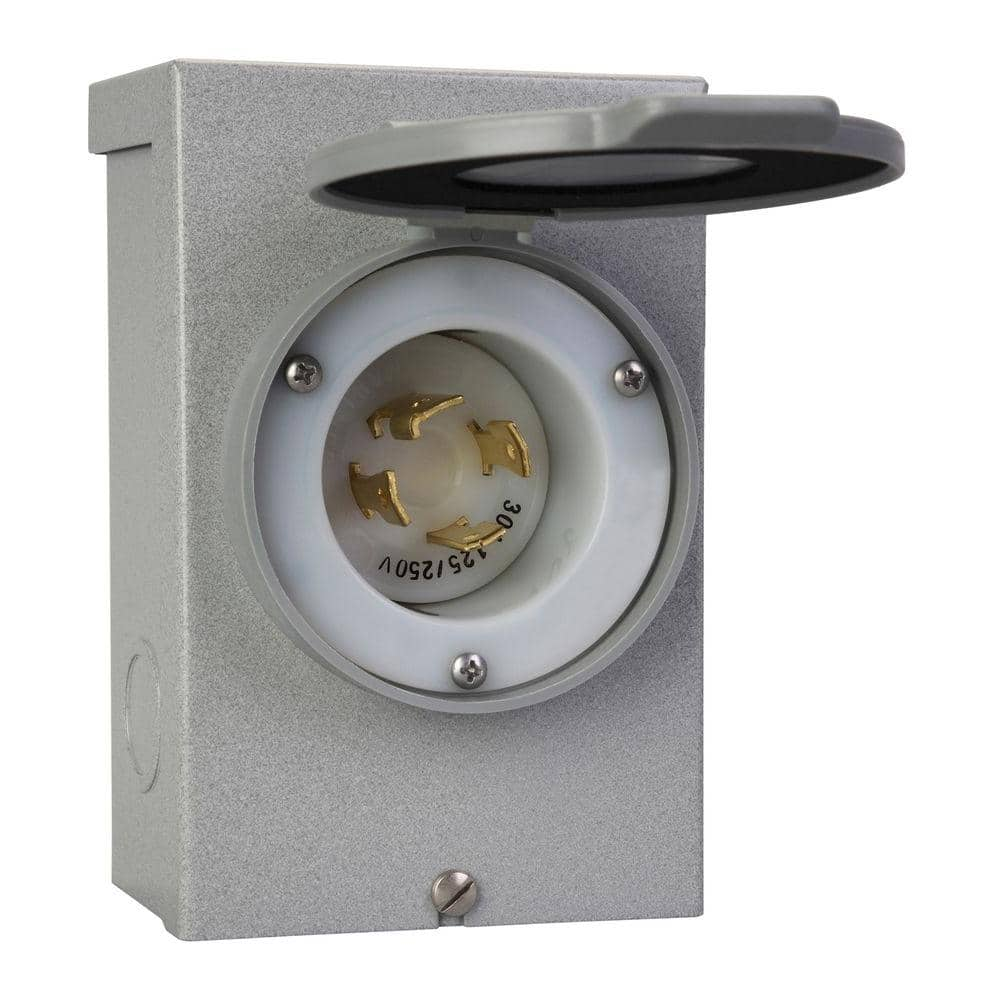
30A:
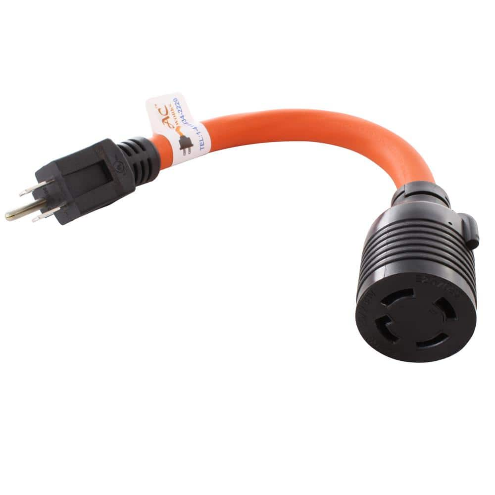
3 to 4 prong adapter:
Is it okay to install these 20/30A boxes inside? The 15A inlet would be flush with the sheetrock and next to my main panel in garage. These outdoor boxes would obviously not be flush.
I was planning on going with this 15 amp inlet:
Leviton 15 Amp 125-Volt Straight Blade Grounding Power Inlet Outlet, Gray 001-05278-CWP - The Home Depot
Leviton's industry leading locking devices of industrial grade plugs and connectors and our V-0-Max line of industrial grade flush receptacles. These devices offer superior performance and long lasting
www.homedepot.com
But I'm thinking about future-proofing with a 20 or 30 amp inlet.
20A:
Reliance Controls 20-Amp Power Inlet Box, PB20 - The Home Depot
This 20 Amp power inlet box is designed for outdoor use and can be hardwired directly to a manual transfer switch or transfer panel, eliminating need for cords running through windows or doors. This raintight
www.homedepot.com
GE 20 Amp Twist Lock Power Inlet T020N - The Home Depot
The GE 20 Amp Power Inlet (L14-20 Twist Lock) features a single enclosure that protects against weather and normal field use. The galvanized steel construction and electro-deposition paint finish prevent
www.homedepot.com
30A:
Reliance Controls 30 Amp Power Inlet Box PB30 - The Home Depot
The Reliance Controls 30 Amp Power Inlet Box is designed for outdoor use and can be hardwired directly to a manual transfer switch or transfer panel, eliminating the need for cords running through windows
www.homedepot.com
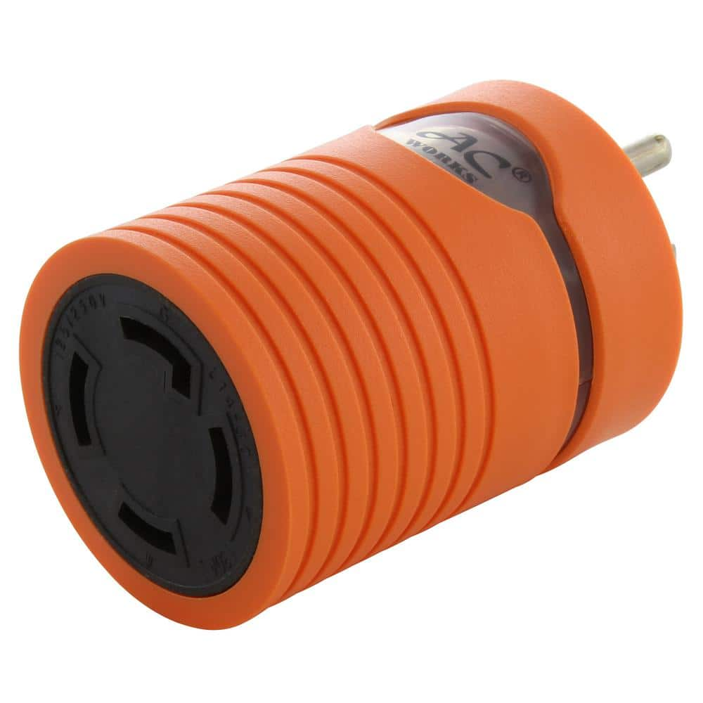
3 to 4 prong adapter:
AC WORKS 1 ft. 15 Amp Household Plug to L14-30 30 Amp 4-Prong Transfer Switch Inlet Adapter S515L1430-012 - The Home Depot
This AC WORKS brand adapter cord [S515L1430-018] is very durable. It is a NEMA 5-15P to NEMA L14-30R. The NEMA 5-15P is a 15-Amp, 125 Volt, 3-prong Household male plug. The NEMA L14-30R (Hots Bridged)
www.homedepot.com
Is it okay to install these 20/30A boxes inside? The 15A inlet would be flush with the sheetrock and next to my main panel in garage. These outdoor boxes would obviously not be flush.
Hedges
I See Electromagnetic Fields!
- Joined
- Mar 28, 2020
- Messages
- 20,670
Don't wire two inlet boxes in parallel, because if generator feeds one, the other would have hot pins exposed.
I think one 20A or 30A 230V inlet would be the way to go, with a 115V cord feeding it.
I also think that feeding a single-phase source to both phases of 115/230V panel is OK so long as source can't provide more than 20A. If it could, then neutral wires might carry more than 20A without protection.
Is inside for inverter, outside for generator? You could have both with wires to the main box, but one capped with wire nuts and not connected to breaker. Or just run extension cord from outside in to use a single inlet.
Any of those boxes could go inside or out, but none come with a wet in-use cover. You would want that if outside and you're going to use generator during rain.
Don't wire two inlet boxes in parallel, because if generator feeds one, the other would have hot pins exposed.
I think one 20A or 30A 230V inlet would be the way to go, with a 115V cord feeding it.
I also think that feeding a single-phase source to both phases of 115/230V panel is OK so long as source can't provide more than 20A. If it could, then neutral wires might carry more than 20A without protection.
Sorry that wasn't clear. I only need 1 inlet box. I'm just thinking it may be prudent to go with something bigger than the 15A just in case.
Is inside for inverter, outside for generator? You could have both with wires to the main box, but one capped with wire nuts and not connected to breaker. Or just run extension cord from outside in to use a single inlet.
Any of those boxes could go inside or out, but none come with a wet in-use cover. You would want that if outside and you're going to use generator during rain.
The inlet box will be inside the garage next to my main panel.
Thanks!
Why do these 4 prong 30A to 3 prong 15A adapters have a maximum power of 1875W? It's not a problem for my current setup but if I had a higher power inverter how would I get more than 1875W into this 30A inlet box?
AC WORKS Locking Adapter Household Plug 15 Amp NEMA 5-15P to 4-Prong 30 Amp Locking L14-30R (2 Hots Bridged) AD515L1430 - The Home Depot
This AC WORKS brand locking adapter [AD515L1430] is a regular household plug to a locking female connector. This product is very durable and has a maximum operating power of 1875 Watts, a built-in power
www.homedepot.com
AC WORKS 1 ft. 15 Amp Household Plug to L14-30 30 Amp 4-Prong Transfer Switch Inlet Adapter S515L1430-012 - The Home Depot
This AC WORKS brand adapter cord [S515L1430-018] is very durable. It is a NEMA 5-15P to NEMA L14-30R. The NEMA 5-15P is a 15-Amp, 125 Volt, 3-prong Household male plug. The NEMA L14-30R (Hots Bridged)
www.homedepot.com
gnubie
Solar Wizard
- Joined
- Sep 20, 2019
- Messages
- 3,847
It's not a good choice of thing (without looking at the linked pages at all). Connecting a cable + plug that is rated for 15A to a circuit that is rated to provide 30A leaves you with the very real possibility that damaging current can be drawn over that cable + plug before the supplying circuit will even think about tripping. If there was a 15A fuse at 30A end of the lead that'd cover that situation. This makes no reference to the voltages that may be present on that 30A socket.
Having not read the links at all I'm assuming supply side is 30A, load side is 15, not the other way around.
You always want an appropriately rated fuse protecting the lowest rated component.
Having not read the links at all I'm assuming supply side is 30A, load side is 15, not the other way around.
You always want an appropriately rated fuse protecting the lowest rated component.
It's not a good choice of thing (without looking at the linked pages at all). Connecting a cable + plug that is rated for 15A to a circuit that is rated to provide 30A leaves you with the very real possibility that damaging current can be drawn over that cable + plug before the supplying circuit will even think about tripping. If there was a 15A fuse at 30A end of the lead that'd cover that situation. This makes no reference to the voltages that may be present on that 30A socket.
Having not read the links at all I'm assuming supply side is 30A, load side is 15, not the other way around.
You always want an appropriately rated fuse protecting the lowest rated component.
So leaving those adapters aside, how would you go from a 3000W inverter to a 30A 4 prong (L14-30) inlet box? The inverters have 3 prong 110-120V (NEMA 5 15P?) plugs right? I know I'm missing something obvious.
Similar threads
- Replies
- 9
- Views
- 321
- Replies
- 10
- Views
- 628