SunFarmer
New Member
Hello forum,
Reached another milestone on my solar power project, and discovered new challenges…
But first: Zoomyn, yes that green box seen behind the solar array is a transformer owned by our local electric utility “BGE”.
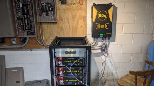
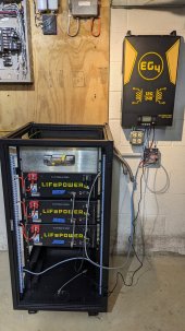
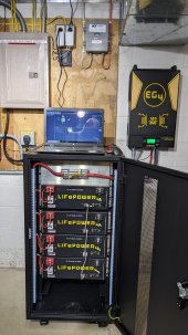
Now for milestone: Installed the battery cabinet, batteries and inverter. Also, partially turned the system on (just one battery) and performed initial tests. Yes, on December 21, the winter solstice, shortest day of the year, I activated my solar power system! The panels produced 3500 watts (15A at 234V) and the inverter spun up and pushed 60A charge current to the battery. With this milestone, I will claim the federal tax credit this year.
For the EG4 battery cabinet, I made a few modifications. The battery instructions states “Connect a grounding conductor to the grounding lug on the rack”. But my EG4 cabinet does not have a ground lug, I looked all over, so I made my own. First, I filed the paint off of the square mounting holes on the left rail to ensure good metal-to-metal contact between the batteries and the rack. Then attached a ground wire and ran it to my compound’s main grounding bus. I had to make another modification, because after lifting three 100lb batteries into the rack, I discovered that the batteries protruded out the back of the cabinet and I couldn’t reinstall the back cover. To remedy this, I flipped the battery mount ears which pulled the batteries forward about an inch, just enough so I could fit the back cover. Lastly, the mounting holes for one of the batteries didn't line up. So, I had to take that battery out again, file the mounting holes on the L-brackets where battery slides on to drop it about 1/8", then put the battery back in and it lined up.
Now for the challenges. I discovered the EG4 6000EX-48HV inverter appears to have and internal neutral to ground bonding jumper for the AC output connection. I measured the N-G resistance and got a dead short. For my house the N-G bond is in the main breaker panel and I’m going to keep it that way, but I’m concerned about a second N-G bond in the inverter. Another challenge, I was planning to repurpose my generator subpanel for solar-powered critical loads. However, as currently configured, there is a common neutral on the generator panel and the main AC panel. For the 6000EX-48HV, this would result in the neutral for the AC input connected to the neutral of the AC output. From what I’m reading in the forum, I want to avoid the common neutral arrangement. I sent a query to Signature Solar Tech Support but haven’t yet heard back from them.
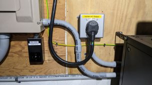
To solve both N-G bond and common neutral issues, I’m reverting to a setup which I previously considered. My plan now is put a 50A 4-prong kitchen range plug and cord on the solar power subpanel and a 50A socket on the main panel, and another socket on the inverter AC output. This way I can plug the subpanel into the inverter for off-grid operation or plug it into the main panel for on-grid operation. Consequently, I’ll be removing and redoing much of the conduit you see in the picture, and I’ll still have to run a line from the main panel to the inverter AC input for automatic failover if the batteries go dead. Any thoughts on this arrangement.
Reached another milestone on my solar power project, and discovered new challenges…
But first: Zoomyn, yes that green box seen behind the solar array is a transformer owned by our local electric utility “BGE”.
Now for milestone: Installed the battery cabinet, batteries and inverter. Also, partially turned the system on (just one battery) and performed initial tests. Yes, on December 21, the winter solstice, shortest day of the year, I activated my solar power system! The panels produced 3500 watts (15A at 234V) and the inverter spun up and pushed 60A charge current to the battery. With this milestone, I will claim the federal tax credit this year.
For the EG4 battery cabinet, I made a few modifications. The battery instructions states “Connect a grounding conductor to the grounding lug on the rack”. But my EG4 cabinet does not have a ground lug, I looked all over, so I made my own. First, I filed the paint off of the square mounting holes on the left rail to ensure good metal-to-metal contact between the batteries and the rack. Then attached a ground wire and ran it to my compound’s main grounding bus. I had to make another modification, because after lifting three 100lb batteries into the rack, I discovered that the batteries protruded out the back of the cabinet and I couldn’t reinstall the back cover. To remedy this, I flipped the battery mount ears which pulled the batteries forward about an inch, just enough so I could fit the back cover. Lastly, the mounting holes for one of the batteries didn't line up. So, I had to take that battery out again, file the mounting holes on the L-brackets where battery slides on to drop it about 1/8", then put the battery back in and it lined up.
Now for the challenges. I discovered the EG4 6000EX-48HV inverter appears to have and internal neutral to ground bonding jumper for the AC output connection. I measured the N-G resistance and got a dead short. For my house the N-G bond is in the main breaker panel and I’m going to keep it that way, but I’m concerned about a second N-G bond in the inverter. Another challenge, I was planning to repurpose my generator subpanel for solar-powered critical loads. However, as currently configured, there is a common neutral on the generator panel and the main AC panel. For the 6000EX-48HV, this would result in the neutral for the AC input connected to the neutral of the AC output. From what I’m reading in the forum, I want to avoid the common neutral arrangement. I sent a query to Signature Solar Tech Support but haven’t yet heard back from them.
To solve both N-G bond and common neutral issues, I’m reverting to a setup which I previously considered. My plan now is put a 50A 4-prong kitchen range plug and cord on the solar power subpanel and a 50A socket on the main panel, and another socket on the inverter AC output. This way I can plug the subpanel into the inverter for off-grid operation or plug it into the main panel for on-grid operation. Consequently, I’ll be removing and redoing much of the conduit you see in the picture, and I’ll still have to run a line from the main panel to the inverter AC input for automatic failover if the batteries go dead. Any thoughts on this arrangement.