diy solar

diy solar

MPP LV6048 Settings ->max charging current & battery equalization (eg4)

nscottsdale

New Member
Joined
Aug 26, 2021
Messages
74
I have my setup detailed here (https://diysolarforum.com/threads/pre-flight-peer-review-16kw-system.54794/#post-712820 )

Question one
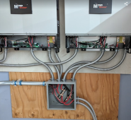
I am working on configuring my pair of LV6048 in a split phase configuration. The two LV6048 battery connections are paralleled on a bus bar that feeds two parallel EG4 batteries.

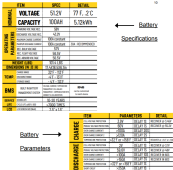
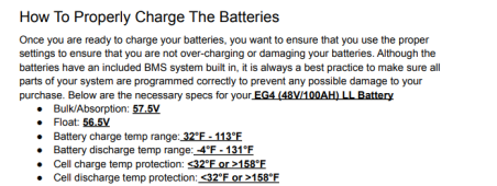
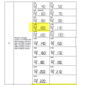
The spec on the EG4 says Max charging current is 100 amps.

I have two EG4’s in parallel , do i set the rate to 100 amps as the lowest safety net or 200 amps because i have two batteries?
Or do i set each LV6048 to 50 amps so that 50 plus 50 = 100?

Question Two

The LV6048 has a setting for "Bulk charging voltage (C.V voltage)" but the EG4 spec has
a)"Charging voltage rec. - 58v"
and
b)"Rec bulk voltage - 57v"
c) Bulk/Absorption 57.5v
Which one to use?


Question Three

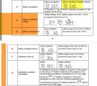
The setting 34 to 39 are for "Battery Equalization". What does this do? It cant possibly see down stream and equalize Batteries that are parallel on the bus.
eg1_15-59-52.png

eg258-42.png
eg4444_16-03-40.png
eg555516-10-31.png
 
MPP replied and said if i have a 100ah battery to set it 20 amps for max charging , ,y follow up question is since i have two 100 ah batteries if it was to be 40 amps.
 
Yes, with 2 batteries in parallel the capacity doubles so 40Amps would still be only a 0.2C charge rate. Also, at 40A even if one battery were to unexpectedly turn off via the BMS or the breaker, the other battery will have to take the full 40A but this wouldn't cause any damage in the short term.
 
Question one
I am working on configuring my pair of LV6048 in a split phase configuration. The two LV6048 battery connections are paralleled on a bus bar that feeds two parallel EG4 batteries.
On page 33 of the MPP 6048 manual, recommended Battery PER inverter is 200Ahr, since you have two inverters, the recommended battery is 400Ah.
Consider each inverter has 27.3A 240VAC output capacity - 6500W x 2 13,000W
To deliver this (even if we assume zero losses, or surge) 13,000/51.2VDC = 254A (ie more than the two batteries can output) so watch how much load you apply, especially motor loads. Perhaps you will be able to add more batteries in the future.
I will suggest you plan the Energy Storage to MPP connections as follows:

Set up two main bus bars, one POS one NEG.
Each battery connects to the bus bars independent of all other batteries (which allows easy service) perferably with equal length/ga. conductors to maintain balance.
Each bus connects to each Inverter, pos to pos neg to neg.
In my system I put a 125A Class-T fuse and a 1P disconnect between each battery pos and the POS bus,
And I put a 300A T-Class fuse and 2P disconnect between each Bus and each inverter.
I have read on the forum that the T-Class may be overkill, especially between the battery and bus, perhaps a ANL fuse block would be acceptable here.
I am not qualified to say for sure, I only know the interrupt current on a Class-T are very high, and this provides a high degree of protection/peace of mind.
 
Thanks - yes the two batteries are a starter set..

I have a 48u cabinet and will need to add a bus bar in there.

zzzz-22-52.png
fff8-23-36.png
 
Yes, I did too, since the batteries are pretty spendy.
It cant possibly see down stream and equalize Batteries that are parallel on the bus
Yes it can, if you install the comms between the battery and the MPP

The MPP's come with factory default settings for Lead-Acid, but these are not appropriate for LiFePO4 so you need to change Setting 05 to "USE" which means 'user-defined' and then change the set points for LiFePO4. See Will's post under DIY LiFePO4 - charge settings. (I list my settings below)

From you pic, I don't see any of the communication cables & current sharing cables between the two inverters, you need these to keep the two inverters in sync (phase) and so they load share. In setting 28 the inverters should be set to 2A2. One MPP unit will be the Master, and the other will be the student, you set this with the dip switches under the bottom cable area (see page 37 of the manual). Also the MPP have communication cables for the batteries as noted above, so the inverter does actually know what the battery SOC temp and current.

You may have disconnects outside of the picture's view that I don't see, if not consider:
PV disconnects (2P) to be able to isolate each incoming PV string of energy if needs be for service or emergency. (in Canada this is code required)
ESS (energy storage system) 2P disconnects between each inverter and the ESS for the same reasons as above.
1P disconnect on the POS of each battery cable between the BUS and the battery - for service or emergency.
and as I already noted above I am a supporter of fuses on each battery, and between the Bus and each inverter.
Hope this is helpful, take it as advice only, you should do your own review and analysis of what you need for your set up.
 
Last edited:
There are a number of posts on the battery settings for LiFePO4 as well as Will's post I mentioned. I follow Andy (Off Grid Garage) on youtube and Andy does a deep dive into all the settings, and backs up his take on the values with his own testing which he shares.
The differences are realatively small, and in some cases influenced by a desire to maximize cycle life of the cells (they are pricy, may as well make them last)
Personnally I use: MPP 6048 setting parameter
Bulk charge 56.0 Setting 26
Float 54.0 Setting 27
Equalize - disabled Setting 33
Setting voltage back to utility 48.0 Setting 12
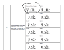
Setting voltage back to battery "FUL" Setting 13
Low DC Cut-off 47.0 Setting 29

I don't say everyone should use the settings I do, I say do your own research and consider what will be best for your system in your situation.
 
Thanks - i will be doing first power on this weekend.

Yes it can, if you install the comms between the battery and the MPP

I need to study on this an re trace my reading. I thought the MPP could not talk to the EG4 BMS

The MPP's come with factory default settings for Lead-Acid, but these are not appropriate for LiFePO4 so you need to change Setting 05 to "USE" which means 'user-defined' and then change the set points for LiFePO4. See Will's post under DIY LiFePO4 - charge settings. (I list my settings below)


I need to research this , Wil prowse video i think said to set to mpp 05 to AGM

From you pic, I don't see any of the communication cables & current sharing cables between the two inverters, you need these to keep the two inverters in sync (phase) and so they load share. In setting 28 the inverters should be set to 2A2. One MPP unit will be the Master, and the other will be the student, you set this with the dip switches under the bottom cable area (see page 37 of the manual). Also the MPP have communication cables for the batteries as noted above, so the inverter does actually know what the battery SOC temp and current.

Confirmed on I still need to do com cables and confirm dip switches. Also confirm setting 28 is planned to be 2A2. For MPP to battery com.. that is something i need to revisit - i thought that was not possible with vendor mismatch. Also i may need to be making longer cables if possible.

You may have disconnects outside of the picture's view that I don't see, if not consider: PV disconnects (2P) to be able to isolate each incoming PV string of energy if needs be for service or emergency. (in Canada this is code required)

Got it - four combiners outside with breaker switch were accepted by city plan as disconnect.

ESS (energy storage system) 2P disconnects between each inverter and the ESS for the same reasons as above.

For now i am using the built in battery breaker for that.

1P disconnect on the POS of each battery cable between the BUS and the battery - for service or emergency.
and as I already noted above I am a supporter of fuses on each battery, and between the Bus and each inverter.
Hope this is helpful, take it as advice only, you should do your own review and analysis of what you need for your set up.


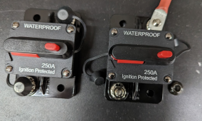
I do have some ebay circuit breaker devices in hand, i will add these in - they looked too lightweight to be real.

... and THANK YOU for taking the time!

3333319-32.png
 
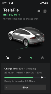
Well as the sun sets, to the west, i imagine the eg4's are shutting down from over current pretty much exactly to calculations .. 40 amps to tesla charger 9600 watts.. and 48 v with two batteries .... so 9600/48 = 200 amps.. and the two packs cant do the deed.
 
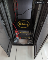
@nscottsdale in your OP, your last photo says it’s the specs for EG4 LL batteries. But your photo shows you have EG4 LiFePOWER4. They are 2 different batteries. I’ll post some information below.

Here is the manual for those batteries, taken from SS website:
https://signaturesolar.com/content/documents/EG4/EG4-Lifepower4 48V-24V Manual-2.3.1.pdf

Page 4 states Bulk: 56.2v. Float: 54v.

But, there has been some different info from people at SS.

This post states 56.2v for all EG4 batteries:

But this post says that LP4 batteries are full at 58v:

@BenFromSignatureSolar can we get a confirmation that Bulk and Float are both recommended be set to 58v (in USE mode) for the LP4? And an update on if the manual will be changed to reflect this?

@nscottsdale here is a post about the amperage for EG4 LL batteries. I imagine it is similar for the LP4 batteries:

I was under the impression they could handle 100a as well, but it seems like you really shouldn’t do that.

For reference, I have 2x EG4 6500 inverters connected to 4x LP4 batteries. When they are in EG4 mode and communicating with each other, the max amperage is limited to 100a from each inverter. That’s 200a total / 4 batteries so 50amp per battery.

in EG4 mode the Bulk and Float are set to 58v but I have never seen it get that high. Usually around 55v the inverters throttle to just 10a charging. Maybe they would eventually get to 58v but i usually turn on a heavy load and havnt really let them charge full to see what happens. That’s why I’m asking @BenFromSignatureSolar to confirm Bulk/Float should be set to 58v in USE mode.

I did run in USE mode for a while and using what was recommended in the LP4 manual (bulk 56.2v / float 54v) seemed to work well.

I hope this all helps
 
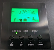
When inadvertently charging my Tesla in the evening, i can exceed the storage of my batteries and per settings made in solarasstant i believe, the inverters go into "standby" mode. At sunrise the batteries do charge, but the invers do not seem to auto come out of standby mode. Is taht a configurable option? Thanks!!!
 
Back
Top