pablo131
New Member
Hi Guys and Gals,
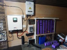
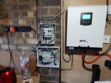
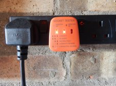
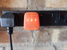
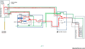
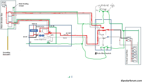
I have a problem here in the uk with my 240VAC system. As you can see from the pictures, I tried to solve the neutral ground bond problem when running on solar and/or batteries by using a transfer switch. Could you gurus please cast an eye over my setup to see where I have failed. The system is working well but.... when on solar/batteries, I have no earth according to the socket tester. I can measure 105VAC between neutral and earth and 122VAC between live and earth. The output is 240VAC give or take 2 volts. All is good when (earth is there on the socket tester) running on mains, either through the MPP or direct. I have an earth.
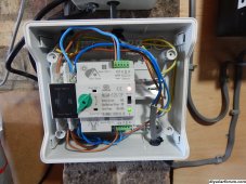
My MPP system only supplies a few select items and does not back feed to the main consumer unit (panel) I only use the grid power to feed the MPP when solar and power is exhausted and the grid also feeds the transfer switch. I thought the internal changeover relay inside the MPP would autobond the neutral to earth when running on solar/battery. It looks like it partially does it as the earth indicator on the socket tester is faintly alight some of the time and the 30mA Residual Current Device RCD protection (in the critical load consumer unit) trips when I push to test
My background was as a marine radio/radar tech and ROV plough pilot technician so I am not completely thick.
I have a problem here in the uk with my 240VAC system. As you can see from the pictures, I tried to solve the neutral ground bond problem when running on solar and/or batteries by using a transfer switch. Could you gurus please cast an eye over my setup to see where I have failed. The system is working well but.... when on solar/batteries, I have no earth according to the socket tester. I can measure 105VAC between neutral and earth and 122VAC between live and earth. The output is 240VAC give or take 2 volts. All is good when (earth is there on the socket tester) running on mains, either through the MPP or direct. I have an earth.
My MPP system only supplies a few select items and does not back feed to the main consumer unit (panel) I only use the grid power to feed the MPP when solar and power is exhausted and the grid also feeds the transfer switch. I thought the internal changeover relay inside the MPP would autobond the neutral to earth when running on solar/battery. It looks like it partially does it as the earth indicator on the socket tester is faintly alight some of the time and the 30mA Residual Current Device RCD protection (in the critical load consumer unit) trips when I push to test
My background was as a marine radio/radar tech and ROV plough pilot technician so I am not completely thick.