I wonder why Onan labels these generators as non-recombinable.Correct, they are in phase with each other, bridging them just gets around the limitations of the breakers for each leg and allows you to use the full power of the generator. Not sure why they designed the mpii to reject l2 power when in phase with l1. I am sure there is a reason...


You are using an out of date browser. It may not display this or other websites correctly.
You should upgrade or use an alternative browser.
You should upgrade or use an alternative browser.
Multiplus-II and Onan QG 5500 design questions/validation
- Thread starter Brother_Bluto
- Start date
triplethreat
Solar Enthusiast
- Joined
- Oct 12, 2021
- Messages
- 129
For any of you that are struggling with this issue, Changing Lanes RV just released a new video yesterday evening and went into detail on how to solve this. Changing Lanes RV is Chad and Tara and they have quite the extensive setup on their Grand Design toy hauler.....2000 watts of solar on the roof, Multiplus II, the Onan generator, 10 Battle Born LFP batteries and much more. Here is a link to their video....

 changinglanesrv.com
RV Off-Grid (Solar) Power System Review and Fixes!
RV Off-Grid (Solar) Power System Review and Fixes! Changing Lanes
changinglanesrv.com
Brother_Bluto
New Member
- Joined
- Jul 23, 2021
- Messages
- 8
Mine is the 5.5HGJAB-6755M; 120V / 45.8a / single phaseWhich specific Model of onan do you have?
corn18
Village Idiot
- Joined
- Sep 9, 2021
- Messages
- 667
I think this is for folks with a 50A RV that use a 30A to 50A dogbone to connect to shore power. The dogbone ties L1 to L2 which sends 120V in phase in L1 and L2 to the MPII. Then the MPII senses this and ties L1 to L2 and passes that to the power center powering both L1 and L2.Correct, they are in phase with each other, bridging them just gets around the limitations of the breakers for each leg and allows you to use the full power of the generator. Not sure why they designed the mpii to reject l2 power when in phase with l1. I am sure there is a reason...
The issue you are having is what to do with the two separate, but in phase, outputs from the Onan. I don't have an easy answer for that.
corn18
Village Idiot
- Joined
- Sep 9, 2021
- Messages
- 667
Could it really be as simple as wiring the generator outputs in parallel?For any of you that are struggling with this issue, Changing Lanes RV just released a new video yesterday evening and went into detail on how to solve this. Changing Lanes RV is Chad and Tara and they have quite the extensive setup on their Grand Design toy hauler.....2000 watts of solar on the roof, Multiplus II, the Onan generator, 10 Battle Born LFP batteries and much more. Here is a link to their video....
RV Off-Grid (Solar) Power System Review and Fixes!
RV Off-Grid (Solar) Power System Review and Fixes! Changing Lanes
It is that simple... Have done it since the mpii came out... Just make sure you confirm no voltage between l1 and l2 and that the combining is done at or before the transfer switch. If done after the transfer switch and you hook into split phase power you might need the fire department...I think this is for folks with a 50A RV that use a 30A to 50A dogbone to connect to shore power. The dogbone ties L1 to L2 which sends 120V in phase in L1 and L2 to the MPII. Then the MPII senses this and ties L1 to L2 and passes that to the power center powering both L1 and L2.
The issue you are having is what to do with the two separate, but in phase, outputs from the Onan. I don't have an easy answer for that.
Could it really be as simple as wiring the generator outputs in parallel?
Brother_Bluto
New Member
- Joined
- Jul 23, 2021
- Messages
- 8
Thanks - I started watching it earlier today... but hadn't gotten to the Generator section. Nice!!For any of you that are struggling with this issue, Changing Lanes RV just released a new video yesterday evening and went into detail on how to solve this. Changing Lanes RV is Chad and Tara and they have quite the extensive setup on their Grand Design toy hauler.....2000 watts of solar on the roof, Multiplus II, the Onan generator, 10 Battle Born LFP batteries and much more. Here is a link to their video....
RV Off-Grid (Solar) Power System Review and Fixes!
RV Off-Grid (Solar) Power System Review and Fixes! Changing Lanes
Apparently it works for people but Onan have repeatedly told me that these units are Non-recombinable. Meaning you can't do exactly what is mentioned in the video however I assume nothing bad has happened with it for him to post a video.Could it really be as simple as wiring the generator outputs in parallel?
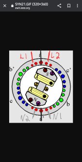
The only thing I can think of, would be that the generators stator has more than 3 poles and is in multiples of 3 like 12 or 24. This would mean that the individual poles between 0-120deg, 120-240deg, and 240-360deg would be wired in parallel. This would mean one line would be energized milliseconds before the other
Attachments
davejowen65
New Member
- Joined
- Oct 10, 2022
- Messages
- 14
Hi Everyone, sorry to drudge up an old post, but it is very specific to my current needs. I have a big boy Onan 10000 QD. Everything I've read about this modification would apply to my situation, but I am getting 240 volts when measured across L1 and L2. I know the generator is single phase (called up Onan). I think this has something to do with what Togo678 and others have posted about the generator alternator having 3 poles that are slightly out of sync (120 degrees).
Can I still combine L1 and L2 to feed my MultiPlus II 2x120?
Can I still combine L1 and L2 to feed my MultiPlus II 2x120?
HighTechLab
AKA Dexter - CTO of Current Connected, LLC
- Joined
- Sep 23, 2019
- Messages
- 1,691
yesHi Everyone, sorry to drudge up an old post, but it is very specific to my current needs. I have a big boy Onan 10000 QD. Everything I've read about this modification would apply to my situation, but I am getting 240 volts when measured across L1 and L2. I know the generator is single phase (called up Onan). I think this has something to do with what Togo678 and others have posted about the generator alternator having 3 poles that are slightly out of sync (120 degrees).
Can I still combine L1 and L2 to feed my MultiPlus II 2x120?
NO!!! If you have 240volts between L1 and L2 on the generator output than the lines should NOT be combined EVER.
If you have voltage between L1 and L2 of 240v than the Multiplus II will handle the power directly. Single phase is technically 240v and your generator has a center tap giving you split phase. Which is the input that the multiplus II is rated for.Hi Everyone, sorry to drudge up an old post, but it is very specific to my current needs. I have a big boy Onan 10000 QD. Everything I've read about this modification would apply to my situation, but I am getting 240 volts when measured across L1 and L2. I know the generator is single phase (called up Onan). I think this has something to do with what Togo678 and others have posted about the generator alternator having 3 poles that are slightly out of sync (120 degrees).
Can I still combine L1 and L2 to feed my MultiPlus II 2x120?
John Frum
Tell me your problems
- Joined
- Nov 30, 2019
- Messages
- 15,233
Do you also get 120VAC between L1 and N?Everything I've read about this modification would apply to my situation, but I am getting 240 volts when measured across L1 and L2.
Also 120VAC between L2 and N?
Is there also a ground wire?
davejowen65
New Member
- Joined
- Oct 10, 2022
- Messages
- 14
Thanks for the input! BTW: love the install you did for Riley and Courtney.
davejowen65
New Member
- Joined
- Oct 10, 2022
- Messages
- 14
I'm having trouble with the MultiPlus randomnly refusing AC inut from my Onan. It is the most infuriating thing I have experienced, as 98% of the time it works perfectly fine, but when that 2% hits, the darn thing will not accept input at all. I have done so many things to get this thing to work when it's acting up. Usually, a completely random enabling and disabling of LOM, UPS Function, Weak AC Input, Wider voltage ranges, etc. will finally get it working.If you have voltage between L1 and L2 of 240v than the Multiplus II will handle the power directly. Single phase is technically 240v and your generator has a center tap giving you split phase. Which is the input that the multiplus II is rated for.
I am pretty sure it has to do with how my generator "occasionally" behaves under no load. Today, the fix was to hook up my secondary 75amp AIMS Converter Charger for about 20 minutes and then enable weak ac input for about 10 minutes, then turn weak ac input off. Charging batteries at 195 amps again.
This is so frustrating, I lost 3 hours of my work day this morning fudging around with it. I am grasping at straws trying to get some consistency. Would love some solid advice...
Ok Dave, let me just start with DO NOT COMBINE L1 AND L2 ON YOUR GENERATOR!I'm having trouble with the MultiPlus randomnly refusing AC inut from my Onan. It is the most infuriating thing I have experienced, as 98% of the time it works perfectly fine, but when that 2% hits, the darn thing will not accept input at all. I have done so many things to get this thing to work when it's acting up. Usually, a completely random enabling and disabling of LOM, UPS Function, Weak AC Input, Wider voltage ranges, etc. will finally get it working.
I am pretty sure it has to do with how my generator "occasionally" behaves under no load. Today, the fix was to hook up my secondary 75amp AIMS Converter Charger for about 20 minutes and then enable weak ac input for about 10 minutes, then turn weak ac input off. Charging batteries at 195 amps again.
This is so frustrating, I lost 3 hours of my work day this morning fudging around with it. I am grasping at straws trying to get some consistency. Would love some solid advice...
Now that that is out of the way. Most likely your settings are incorrect. Could you please upload some screen shots or the actual veConfig file for your system?
davejowen65
New Member
- Joined
- Oct 10, 2022
- Messages
- 14
Yes, to all. Wiring out of the generator is G,N,L2,L1Do you also get 120VAC between L1 and N?
Also 120VAC between L2 and N?
Is there also a ground wire?
davejowen65
New Member
- Joined
- Oct 10, 2022
- Messages
- 14
I'm savvy enough to know not to combine them. That's why I spoke up. This is today's configuration, BTW... Likely to change next time the MultiPlus acts up...Ok Dave, let me just start with DO NOT COMBINE L1 AND L2 ON YOUR GENERATOR!
Now that that is out of the way. Most likely your settings are incorrect. Could you please upload some screen shots or the actual veConfig file for your system?
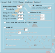
The only thing abnormal on these screenshots is that I have the inverter output voltage lowered in hopes that it would have some affect on the voltage/hz sync...
Like I said, grasping at straws....
Attachments
davejowen65
New Member
- Joined
- Oct 10, 2022
- Messages
- 14
If you prefer, here's this...
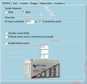
TAB: GeneralSystem frequency 60Hz
Shore current 50.0 A
Overruled by remote checked
Dynamic current limiter unchecked
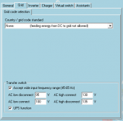
External current sensor connected (see manual) uncheckedTAB: Grid
Country / grid code standard None: (feeding energy from DC to grid not allowed)
Accept wide input frequency range (45-65 Hz) checked
AC low switch mains off 95 V
AC low switch mains on 100 V
AC high switch mains on 130 V
AC high switch mains off 135 V
UPS function checkedTAB: Inverter
PowerAssist checked
Assist current boost factor 2.0
Inverter output voltage 118 V
Ground relay checked
Inverter DC shut-down voltage 11.10 V
Inverter DC restart voltage 11.80 V
Low DC alarm level 11.80 V
Do not restart after short-circuit (VDE 2510-2 safety) unchecked
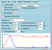
enable AES uncheckedTAB: Charger
Enable charger checked
Weak AC input unchecked
Stop after excessive bulk unchecked
Lithium batteries checked
Configured for VE.Bus BMS unchecked
Charge curve Fixed
Absorption voltage 14.40 V
Float voltage 13.80 V
Charge current 120 A
Repeated absorption time 0.25 Hr
Repeated absorption interval 7.00 Days
Absorption time 1 Hr
Stop charger below 5.0 deg CTAB: Virtual switch
TAB: Usage
Virtual switch usage Do not use VS
TAB: Assistants
TAB: Assistant Configuration
Assistants not used
TAB: GeneralSystem frequency 60Hz
Shore current 50.0 A
Overruled by remote checked
Dynamic current limiter unchecked
External current sensor connected (see manual) uncheckedTAB: Grid
Country / grid code standard None: (feeding energy from DC to grid not allowed)
Accept wide input frequency range (45-65 Hz) checked
AC low switch mains off 95 V
AC low switch mains on 100 V
AC high switch mains on 130 V
AC high switch mains off 135 V
UPS function checkedTAB: Inverter
PowerAssist checked
Assist current boost factor 2.0
Inverter output voltage 118 V
Ground relay checked
Inverter DC shut-down voltage 11.10 V
Inverter DC restart voltage 11.80 V
Low DC alarm level 11.80 V
Do not restart after short-circuit (VDE 2510-2 safety) unchecked
enable AES uncheckedTAB: Charger
Enable charger checked
Weak AC input unchecked
Stop after excessive bulk unchecked
Lithium batteries checked
Configured for VE.Bus BMS unchecked
Charge curve Fixed
Absorption voltage 14.40 V
Float voltage 13.80 V
Charge current 120 A
Repeated absorption time 0.25 Hr
Repeated absorption interval 7.00 Days
Absorption time 1 Hr
Stop charger below 5.0 deg CTAB: Virtual switch
TAB: Usage
Virtual switch usage Do not use VS
TAB: Assistants
TAB: Assistant Configuration
Assistants not used
Similar threads
- Replies
- 13
- Views
- 906
- Replies
- 2
- Views
- 647
- Replies
- 13
- Views
- 584