diy solar

diy solar

Nearly there - Equipment Grounding

ruralsolar

New Member
Joined
Jan 16, 2023
Messages
106
Location
Upstate New York
Not sure why I can't figure out the proper grounding for my system. I have two arrays, Sinclair Adjustable Ground mount with 3 posts per array. I was advised I can run a #6THHN from Array 1 to Array 2 where I have my disconnects to a grounding bar and then down to a grounding rod. The real question I have is, what combining do I need to do on the array itself? Do I need to "link" the 3 posts on each array along with a "link" to the purlins with all of that going to the grounding rod? If accurate, since I used the clamps for holding the panels to the purlins I do not need to ground each panel. Thoughts on what I'm missing?
 
I think the most important is to run a ground wire from the array back to the inverter or SCC, sized to carry continuous fault current.

The PV frames are supposed to be bonded to that wire, which is sometimes done with "WEEB" or other methods to bond to mounting rails and use the as conductors.

I'm not sure to what extent other metal in the mounts are required to be bonded. Wires could rub through and short to parts they can touch. Steel parts assembled with threads, screws, or clamps should be bonded well enough for their own grounding, but anodized aluminum requires something that bites through.
 
All metal parts at the array must be grounded. This includes (but is not limited to) , panel frames, racking, metal enclosues, and conduit.
Grounding is provided by running an EGC (equipment grounding conductor) with the PV wires back to the location of the SCC (Solar Charge Controller). And connecting it to your existing grounding system.
If you choose to install an auxiliary ground rod at the array (allowed but not recommended). It must also be connected to the EGC.
All of the EGC at the array, that is exposed to physical damage (not in conduit). Must be a minimum size of #6 AWG. When protected (inside conduit or enclosures), it can be sized by the available fault current.
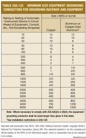
Use this chart for the proper size.
7uqFA.jpg
 
Those minimum grounding conductor sizes presume OCP which will interrupt the current. That is not the case for PV, because OCP is sized at least 1.56x Isc.

Most DIY systems can get away with following the table, because up to 40A, the wire's ampacity can handle the current.
If a home run wire is designed to carry more than 40A, I'd suggest making the grounding conductor same size as current carrying conductors or at least large enough to have the ampacity.

A large system with combiner box at array could have 100A or more for home run. Fed by individually fused strings, but those fuses only blow for faults in certain places. Home run ground wire should be large enough carry current continuously.

More common for us would be multiple runs for separate strings, either to separate MPPT or to a combiner box at the inverter. In that case, have to decide if we want to protect against a fault in all strings at once, or just one.

I anticipate putting 5 strings on my roof to two inverters. The exposed ground wire will be 6 awg solid. I'll just use 6 awg stranded for the short (25') run back to equipment.
 
Those minimum grounding conductor sizes presume OCP which will interrupt the current. That is not the case for PV, because OCP is sized at least 1.56x Isc.
The sizes on the table are based on OCP.
If the OCP is larger, the EGC will also be larger.
 
Hmm ...
That's OK if the OCP trips.
But if I have 200A OCP for a PV array that delivers 128A, I wouldn't want 6 awg carrying the current.

I would say, if OCP is expected to not trip, size ground wire with ampacity to carry the current continuously.

This would be most applicable where you have a combiner box at the array and one pair of home-run conductors.
This isn't a DC ground. This is for possible AC fault current. The ground conductor is not going to carry the current for more than a split second. This is why they are not required to be the same size as the current carrying conductors. I have seen a #12 carry the short circuit current to trip a 200a breaker. (Don't try this at home) it did get a little warm. Because it was horribly undersized. But it wasn't damaged in any way.
 
Not sure why I can't figure out the proper grounding for my system. I have two arrays, Sinclair Adjustable Ground mount with 3 posts per array. I was advised I can run a #6THHN from Array 1 to Array 2 where I have my disconnects to a grounding bar and then down to a grounding rod. The real question I have is, what combining do I need to do on the array itself? Do I need to "link" the 3 posts on each array along with a "link" to the purlins with all of that going to the grounding rod? If accurate, since I used the clamps for holding the panels to the purlins I do not need to ground each panel. Thoughts on what I'm missing?
Your Sinclair racks carry a UL 2703 rating for grounding conductivity-the rack is assembled with serrated flange hardware and the panels are affixed with serrated flange hardware to the purlins. A EGC from the frame of the racking to a ground bar and then from the ground bar along with your PV home runs back to your inverter is sufficient. For your array grounding
 
Your Sinclair racks carry a UL 2703 rating for grounding conductivity-the rack is assembled with serrated flange hardware and the panels are affixed with serrated flange hardware to the purlins. A EGC from the frame of the racking to a ground bar and then from the ground bar along with your PV home runs back to your inverter is sufficient. For your array grounding
Heard back from a person I'm working with on this project. He concurs with needing to tap a grounding lug to one of the array posts, then "joining" those posts with #6 then tapping that into a ground rod at the array, also then coupling a #10 from the array to in house ground point.
 
Heard back from a person I'm working with on this project. He concurs with needing to tap a grounding lug to one of the array posts, then "joining" those posts with #6 then tapping that into a ground rod at the array, also then coupling a #10 from the array to in house ground point.
I would not recommend the auxiliary ground rod at the array. It increases the risk of damage to your equipment. From the gradient pulse, created by a nearby lightning strike. But that's unavoidable if you're racking system includes metal support posts, placed in the earth. in that case you are already connected to the local earth multiple times. And an auxiliary ground rod doesn't change anything, either way.
 
I would not recommend the auxiliary ground rod at the array. It increases the risk of damage to your equipment. From the gradient pulse, created by a nearby lightning strike. But that's unavoidable if you're racking system includes metal support posts, placed in the earth. in that case you are already connected to the local earth multiple times. And an auxiliary ground rod doesn't change anything, either way.
It was commented on about having a ground rod at the array site, it's more so to ensure good ground for the equipment (even though, yes, the posts are in the ground themselves). My array is setup in the middle of a field ~180ft from my house, if lightning strikes the array I'd rather it for sure travel to the array ground rod versus traveling to inside the home ground.
 
it's more so to ensure good ground for the equipment
It doesn't improve electrical grounding at all.
even though, yes, the posts are in the ground themselves
This is actually a disadvantage.
My array is setup in the middle of a field ~180ft from my house, if lightning strikes the array I'd rather it for sure travel to the array ground rod versus traveling to inside the home ground.
Whether lightning strikes the array, or just nearby.
Any earth connection at the array, puts the equipment in the house at risk. From the gradient pulse created.
Hopefully you are installing high quality SPD'Ss on the wires, where they enter the house.
Actually, they can't protect against the gradient pulse that you are inviting on the ground conductor.
 
Back
Top