diy solar

diy solar

Need Advice on Mounting Solar Panels to Wooden Frame and Grounding Off-Grid System

Thank You for all the advice and help. I have quickly learned that there is more to this than throw it on the ground and plug it in. You two are invaluable and absolutely necessary for the successful conclusion for the proper operation and safety of this system.

I have allot of social events with allot of people and I can just see people walking down to the panels and getting all "touchey feeley" with things.

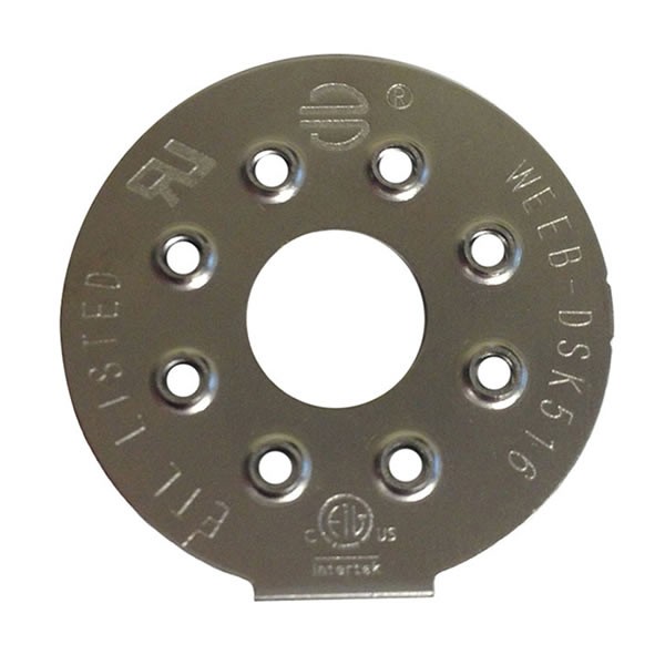
I need to investigate WEEBS a bit further to see if there is a solution there instead of the Ilsco solution. I also don't like the idea of 4 conductors coming into the box. If I configure this right, I should be able to get down to 2, both being continuous runs.

Off to WEEBS school to try and figure those things out.
 
I need to investigate WEEBS a bit further to see if there is a solution there instead of the Ilsco solution. I also don't like the idea of 4 conductors coming into the box. If I configure this right, I should be able to get down to 2, both being continuous runs.
The nice thing about solar EGCs is that you have a lot of flexibility in how to splice them. It doesn’t have to be done inside a junction box. You can probably even find some weather rated split bolt or similar hardware to splice them together within the array.

Is this a DC or AC system? If people are walking around it I would be pretty anxious even with AC modules/microinverters (AC provides slightly more active protection against weird stuff happening).

Usually when I see solar arrays in public here in California and elsewhere, where there is foot traffic, they are way way up out of the way.
 
These are the new 6000XP's, AIO units. Non isolated that like to bleed AC onto the PV lines.

Looking at WEEBS lugs, the 6.7's, they are just as expensive as the Ilsco lugs. They would also need to be mounted via drilling a hole through both the rack and panel (since the panel lays on the angle) and bolt it on with the piercing plate tucked up in there on the inside of the bottom of the panel frame.

On the other hand:

When I spoke to tech at Ilsco, they said using their lug to clamp both the panel and the rack together would violate NEC. I have to wonder how though, if the piercing pad is scratched into the panel frame, what diff does it make where the other side is? I was still planning to use more of them to bond the rack as well.

ETA: By the same logic, bolting the WEEBS on both the panel frame and through the rack should also violate NEC.

Guess I just need to get some in my hands and see which makes the most sense and work the best.
 
Last edited:
Bonding can not be part of the mounting. Because if the mounting loosens you lose the Bonding.
The only exception is weebs, which have somehow been accepted for this use.
Keyword - "somehow" wonder who made out on that deal... typical.

An airplane would have to smash into these racks to loosen them up.

Imagine a 13' long panel, 40" wide. This is the panel layout, 2 panels stacked on short sides x 16 stacks of 2, along the line, over 50 feet or so.

If I could keep the bonding runs in the middle of that 13 foot panel, (2 bonds real close) I can keep wire lengths to a minimum and it will look good. But this would mean clamping to the panel and the rack.

If I cant use 2 clamps on two panels near the middle of that 13' where the panels meet, I have to go to the ends and will have 13' wire runs. Just so happens the rack angles are 12.5 feet long and the two panel stacked on top of each other are 13.5 feet. The panels will overhang the rack by a foot or so on each end and this is the only part of the panels I have open access to just the panel frames, with no rack in the way. This will look like crap and I'll have to use an extra 100' of wire, at least. Guess I could use jumpers between the panels and only bond at one end instead of the middle or on both ends.

I am not having this inspected but still want to abide by the code. I have 2 Union electricians at my disposal to handle the AC end of this quagmire.
 
Last edited:
Keyword - "somehow" wonder who made out on that deal... typical.

An airplane would have to smash into these racks to loosen them up.

Imagine a 13' long panel, 40" wide. This is the panel layout, 2 panels stacked on short sides x 16 stacks of 2, along the line, over 50 feet or so.

If I could keep the bonding runs in the middle of that 13 foot panel, (2 bonds real close) I can keep wire lengths to a minimum and it will look good. But this would mean clamping to the panel and the rack.

If I cant use 2 clamps on two panels near the middle of that 13' where the panels meet, I have to go to the ends and will have 13' wire runs. Just so happens the rack angles are 12.5 feet long and the two panel stacked on top of each other are 13.5 feet. The panels will overhang the rack by a foot or so on each end and this is the only part of the panels I have open access to just the panel frames, with no rack in the way. This will look like crap and I'll have to use an extra 100' of wire, at least.

I am not having this inspected but still want to abide by the code. I have 2 Union electricians at my disposal to handle the AC end of this quagmire.
Just make sure that everything is bonded together. And then the ground conductor only needs to connect to one place.
 
Thanks Tim for your help. Everything else has been resolved pretty eloquently, this however is quickly becoming a cluster ....
 
Just keep it simple. Since you're not needing to pass an inspection.
The goal is to make sure that all metal parts are connected to a path back to your grounding system.
When you bolt the panels to the framing. Put a star washer between the frames. It will bite into both sides and bond them together. (At 4 places per panel) then just attach the ground conductor (at one place) anywhere that is convenient.
 
Living on a knoll and with such a target rich environment, LUCK runs pretty damn thin around here!

Over the years I have installed a few thousand dollars worth of mechanical lightning mitigation systems around here. They have served me well so far. I'm not talking about those little boxes with "special mix) toroid's or beads either. Any one that thinks those things will serve any value against lightning, much less a EMP of duration, is spitting in the wind.

I was thinking of writing up a little description of what I have done around here to mitigate strikes/damage. I have been dealing with lightning for over 50 years in all the data systems design and installations.

ETA: I have noticed searching the forum for "array lightning protection" yields very few results. That's all you need to know...
I would like to see this
 
I would like to see this
Lightning protection is part science and part art. If you want to protect something, give it other, DIRECT, paths to ground.

There isn't really much to see, other than conductors running down towers, a wall or down antenna mast's. Most everything that counts is in the ground. Other than that, I installed lightning arrestors on all high frequency antenna feeds, on the braided shields, to ground. I don't know how well they would do with a strike. A direct hit would blow them to pieces and probably roach anything in the shack that is connected. When storms come around, everything gets pulled if I'm around.

On the mains power, I have some huge MOV's on the incoming mains. These are one shot devices and quite expensive.

Here are some suppliers I have used over the years. NEC has information on mitigation as well.


ETA: Here is an example of proper tower grounding, ironically for a wind turbine. I followed a resemblance of this on 2 towers, as well as using exothermic welds.

https://www.solacity.com/grounding/
 
Last edited:
30 years ago I worked putting up 400' towers for cell phones. The grounding is extensive. For the guyed towers there was a loop around the main base and control building about 10' out. And there was a loop around each of the bases for the guy wires. And a leg from the center tied to each guy. All done in 4/0 copper with 16' rods (if we didn't hit bedrock) every 20' all thermite welded together.

We also did a few free standing towers but I don't remember what the grounding was for them.
 
So after getting spanked for running off the rails with this thread and on the hunt for grounding hardware for the panel rack I am building, I happened across these. They have to be better than star washers but if each panel needs 4, that's a butt load of scratch for half a handful of stainless, like $170 for 32 panels. Wonder if I could just get away with one or 2 per panel?


Then there are these chicom deals. $15 for 50... With allot more "digging in" contact potential.

 
there is more to this than throw it on the ground and plug it in.
This would be a kewl introductory sentence to a solar kit sold online, "Just throw it on the ground and plug it in!!". I could just see thousands sold, then shortly thereafter the complaints, and the seller nowhere to be found.
 
Are there calcs to determine how many square inches, amount of pressure, etc? Or could even just one be fine, as long as all are connected?
Only one connection to each item is required.
The second one provides redundancy.
 
Back
Top