Maybe the system was design to be 24V, and a 12V inverter was accidentally listed or ordered.
At 24V, the Classic 250 charge controller is good for about 1700 to 1800W.
3100W (STC) of panels might produce 2700W under actual conditions. That is just reasonably over-paneled, makes up for days and seasons of less sun.
If the two series strings of 5 PV panels were oriented differently, like 9:00 AM and 3:00 PM sun, then just about all power produced could be used. And battery charge rate would approach optimum more hours of the day (63A from charge controller, 85A target for battery).
Perhaps a modification of the ground mount could change angle of the panels in groups of 5. Different times of day difficult to do with those two rows of 5, and don't want to tilt toward cabin which would shade it. But could tilt 5 optimal for winter and 5 optimal for summer.
MidNite Solar is the industry leader and manufacture of quality Renewable Energy System electrical components and E-Panels.

www.midnitesolar.com
I don't believe having all the panels connected as they are now will damage the SCC. They provide 200 Voc, about 160 Vmp, which is OK. (Midnight 250 allows 250 Voc)
They can deliver 15A, which the SCC could handle fine (Midnight can deliver 63A.)
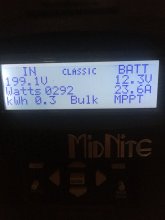
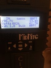
They won't ever deliver 3000W. The most that comes out of Midnight to the battery is 63A x 15V or so, 945W.
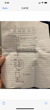
Excess watts won't be dissipated in Midnight either; a "Buck" circuit simply turns on a transistor connecting 180V PV (and a paralleled capacitor) to battery through an inductor, waits until current rises to 60A (comes from capacitor not PV), then turns off transistor. 60A continues to flow through inductor (that's what inductors do) and through a diode to negative. The transistor is on for maybe 1 millisecond, off for 11 milliseconds. 15 A at 180V flows from PV panel to capacitor for 12 milliseconds. 60A at 15V flows to battery for 12 milliseconds. 60A at 180V flows from capacitor to inductor for 1 millisecond.
The only somewhat higher than normal stress is that transistor is switching between 15V and 180V at 60A. (most of transistor's power is dissipated during switching.) If used with a 48V battery where this PV array would be right sized, transistor would switch between 60V and 180V at 60A. With a 12V battery the power dissipation of the transistor is about 1/3 higher than with a 48V battery. Not a big deal.


")