diy solar

diy solar

Need help with A/C Neutral and Ground w/Growatt inverter...


Remove the grounding electrode at the subpanels and eliminate any N-G bond. Leave the N-G bond at the main service panel at the meter.

Edit: Leave grounding electrode at the subpanels but eliminate the N-G bond.
 
Last edited:
First, he said it was correct to have the home's service panels bonded because the primary service feed (the meter) is on a detached building with no metallic conductor (other than the service feeds) between them.
That is not my understanding and it is not my experience. However, the code is very complex and hard to read..... maybe there is a clause that allows or requires the extra bonds but I can't find it and it violates everything I thought I understood about bonding.
 

Remove the grounding electrode at the subpanels and eliminate any N-G bond. Leave the N-G bond at the main service panel at the meter.
I love watching Holt's videos. He does a great job of explaining the WHY behind the code. When I first started teaching myself about grounding, there were a lot of things that made no sense to me. Holt's videos not only helped me understand a lot of the requirements, but he also helped me understand that some of the requirements in the code are not well supported by science. This was a surprise to me because I assumed the NEC had something as 'simple' as grounding figured out a long time ago.

In this particular video, he is talking about 'auxiliary' electrodes. The earth grounding at separate structures is not an auxiliary electrode. It is required to meet all of the requirements of an electrode. However, his description of the problems of auxiliary electrodes applies to the earth grounding of separate structures. There is legitimate debate about whether the separate structure earth grounding requirement is appropriate...but for now it is required.
 
  • Like
Reactions: Zwy
I agree the loop is probably inevitable, but the conductivity of earth has nothing to do with the loop. That part of his statement is nonsense.


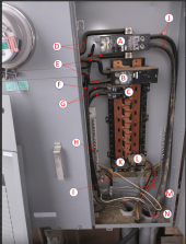
I am struggling to understand what I am seeing in the photo.

View attachment 81455

A) A 200A 2-pole breaker that is independent of the rest of the panel (This is unusual to see but is probably the only way they could do the additional circuit without changing out the whole box. Some inspectors don't like this.)
B) The 200A 2-pole Main Breaker for the panel
C) A 2-pole ??A Breaker on main panel. (I can not see the amperage, but based on the wire size it must be large.)
C feeds a feeder circuit. Must be the house.
D) 240V feed from the Utility (Where is the associated Neutral from the utility?)
E) 240V Feed from the Utility. (Where is the associated Neutral utility?)
F) Unused heavy gauge wire pair

They are used, each goes to a separate conduit.
G) ??? 240V Feeder to other Where???? (Where is the associated Neutral and ground?)

Probably goes to another outbuilding. Smaller conduit.
H) ???Connection to the Ground bar. (Is that the Neutral from the utility?)
I) ??? Wire from ground bar to Where??? (The white band marking on it indicates it is a neutral. Is this the neutral for circuit G?)
Yes, white tape, appears to be neutral for the feeder circuit.

Did you notice the grounding busbar under the letter I? Is this where the N-G bond is occurring? Green screw is on the neutral busbar behind it. Strange.
J) ?? Feeder to Where?? (Where is the associated Neutral and ground?)

Looks to be one of the F wires but don't see any connection to N in the box. Inside the meter socket?
K) 20A?? single-pole Breaker (I am guessing 20 due to wire size)
L) 30A?? dual pole breaker (I am guessing 30A due to wire size)
Connected to M, I'll guess for building this is attached to.
M) ??240V 30A? Circuit with Neutral and ground to where? (That looks like 10AWG, but my eyes are not very well calibrated)

Bigger than 10AWG, looks to be 6AWG maybe. I'll wager this is for the building the panel is attached to.
N) ??120V 15A? Circuit with the ground and neutral to where? (That looks like 14AWG.....)
Neutral goes to H
I am trying to figure out what wires are going to the other building, and for each of the two circuits, where are the Neutral and Ground?
Also, as a curiosity, what feeds the building the box is attached to.
Very confusing, the smaller conduit has quite a few wires in it, my assumption is it goes to the 2 panels at the house.
 
Third, there could be a ground loop between the house panels and remote meter but there really isn't anything reasonable to do about it. Because of the distance (about 100' of cable distance) and earths poor conductivity, this should be of minimum concern.
Here we go again with a complete lack of understanding of what the NEC is trying to do to protect us. It is a serious concern because a lightning strike near by will cause a massive differential in voltage between the 2 ground rods. It is up to you and your sparky to decide if this needs to be dealt with.
Again 99.99% of the time it does not matter and your bulbs will light and your motors whirr happily away, BUT at that 1 moment in life where it does matter, the shit will hit the fan.
Having said all that, a close by strike you really are in the hands of god coz the lightning will do whatever it pleases. I watched a strike hit the nearest pole to my hose and left me almost un-touched where as the house on the other side of the pole took the full brunt of it.
I was also amused at school because our physics teachers house got hit and it blew everything electrical to smithereens. Wires blown out of the wall too.
 
I love watching Holt's videos. He does a great job of explaining the WHY behind the code. When I first started teaching myself about grounding, there were a lot of things that made no sense to me. Holt's videos not only helped me understand a lot of the requirements, but he also helped me understand that some of the requirements in the code are not well supported by science. This was a surprise to me because I assumed the NEC had something as 'simple' as grounding figured out a long time ago.

In this particular video, he is talking about 'auxiliary' electrodes. The earth grounding at separate structures is not an auxiliary electrode. It is required to meet all of the requirements of an electrode. However, his description of the problems of auxiliary electrodes applies to the earth grounding of separate structures. There is legitimate debate about whether the separate structure earth grounding requirement is appropriate...but for now it is required.
You're correct, as this is a multi branch circuit, then it needs a grounding conductor. In my case, the Ufer is grounding conductor and it not bonded to N. It merely connects to the G busbar and interconnects with the grounding conductor.
 
1643313297028.png

Trying to make sense. Let me try to figure this out. You said this is a 400A service?
A & D: 200A circuit from Meter/Utility to Panel 1 via J
B & E: 200A circuit from Meter/Utility to Panel bus bars
C & G: Well circuit?
F: No connection?
H: Looks like a ground wire? Is this wire connected to a ground rod?
I: Neutral from meter base/utility? Neutral for circuit C&G? Looks too small for 400A utility Neutral. Is the neutral bonded to grounding bar? The photo isn't clear enough to tell.
J: To Panel 1?
K & L: Shop Circuits?
M: This looks like an extension cord wired into the panel?
 
I think I can see it now. C & G is the 125A circuit going to Panel 2 with "I" as its neutral. Making the photo larger, I think I can see the bond to the ground bar. "L" is the well circuit?

Bonding NG in Panel 1 & Panel 2 makes sense with two independent circuits. Although I haven't seen a 400A meter base separated by 100 feet from the panel.

Verify this: "...he said there is no N-G bonding taking place inside the Growatt inverter. At least for my model that does not have a N on the input." Check the "N" for AC out and the "G" ground connection with an ohm meter.
 
I think I can see it now. C & G is the 125A circuit going to Panel 2 with "I" as its neutral. Making the photo larger, I think I can see the bond to the ground bar. "L" is the well circuit?

Bonding NG in Panel 1 & Panel 2 makes sense with two independent circuits. Although I haven't seen a 400A meter base separated by 100 feet from the panel.
It is fun to guess what is what in that box, but I will wait to see what the OP says.
 
In my case, the Ufer is grounding conductor .....
As an aside. UFER grounding is considered one of the lowest resistance and most stable ways to do it. It was originally developed by the military (I think it was for Bomb Depots in dry climates). The encasement in concrete means the rebar is very stable and does not deteriorate over time. When I first heard about these I thought the concrete would be too good of an insulator, but apparently not. The concrete will conduct and the sheer size of the contact area to the rebar makes for an excellent connection to earth ground.
 
As an aside. UFER grounding is considered one of the lowest resistance and most stable ways to do it. It was originally developed by the military (I think it was for Bomb Depots in dry climates). The encasement in concrete means the rebar is very stable and does not deteriorate over time. When I first heard about these I thought the concrete would be too good of an insulator, but apparently not. The concrete will conduct and the sheer size of the contact area to the rebar makes for an excellent connection to earth ground.
Correct. Herbert Ufer worked for UL and helped the military lower ground resistance in poor soil.
 
One more observation: Box 2 has a 125A feed. The 12K inverter is the rough equivalent of a 50A feed. I do not know what loads are on box2, but you may have to shut some things down when being powered by the inverter.
 
Ultimately it is best to have only 1 ground rod, but if you need more they should ALL BE CONNECTED with very stout copper wire.
When connecting 2 grounding electrodes (rods) should the connection be buried? Solid or stranded? Bare or insulated? What would be the max distance between 2 grounding electrides (rods)?
 
When connecting 2 grounding electrodes (rods) should the connection be buried? Solid or stranded? Bare or insulated?
I don't think the code requires solid or stranded but I would think solid would be better from a corrosion point of view.
Typically the electrode bonding jumper connection between the two rods is buried but I do not know if that is a requirement.
I don't think the code requires either bare or insulated.

What would be the max distance between 2 grounding electrides (rods)?
I don't think there is a max distance.... but there is kinda a min distance. The code requires 25 ohms of resistance or less. However, the code does not specify the distance between rods. It turns out that if you put two rods right next to each other, the resistance will not be much lower than just a single rod. The rule of thumb is that the rods should be as far apart from each other as they are long. Therefore, if you are using 8' rods, the rods should be at least 8' apart.

BTW: the code requires anything that could act as a grounding electrode to be tied into the earth grounding scheme.
  • Metal Pipes
  • Concrete rebar (on new construction)
  • Steel structural beams sunk into the ground
  • etc
BTW2: In many areas, it is difficult to get below 25ohms with a single rod. It is common for inspectors to just require two rods and never measure the resistance.
 
Been following this thread with interest since my service also starts with a pedestal, which is then split into two feeds of 3 wire triplex feeding 1) a shop, 2) the house. Let's just say, I am all kinds of kornfused. The triplex is only three wires so there is no ground wire to connect the feeder? panels with the pedestal. Not sure about the house or pedestal, yet. Is it safe to only have three wires from the pedestal to the other panels?

 
First, he said it was correct to have the home's service panels bonded because the primary service feed (the meter) is on a detached building with no metallic conductor (other than the service feeds) between them. Since both panels 1 and panels 2 are fed independently and deliver their local circuits independently, it was correct that both are N-G bonded. Also, should be grounded at both ends as it is. Looking it up on-line as well, it dos seem that detached structure sub-panels are to have N-G bonded. So it sounds to me like the electricians did it correctly.
Edited to clarify I was only talking about the NG Bonds.
OK folks, I started doubting myself, but I can now definitively say there should not be N-G bonds at both ends. I did some searching and found this:

250-32(b)(1) Feeder Equipment Grounding Conductor. An equipment grounding conductor (bonding wire) [250-118] installed with the feeder conductors to the separate building or structure can be use to provide the low impedance path to clear a phase-to-ground fault. To prevent dangerous neutral current from flowing on the metal parts of the electrical system, the grounded (neutral) conductor at the separate building or structure must not be bonded to either the equipment grounding conductor or to the grounding electrode system,
Mike holt is very well respected and very active in writing the NEC so I trust what he says. However, it is an old article so I looked at 250-32(b)(1) in the 2020 version of the code. The wording is different but with the same meaning (but the wording is harder to understand)

250-32 Buildings or structures supplied by a Feeder(s) or Branch Circuit
250-32(b) Grounded Systems
250-32(b)(1) Supplied by a Feeder or Branch Circuit (Last sentance)
... Any installed grounded conductor shall not be connected to the equipment grounding conductor or the grounding electrode
A 'grounded conductor' is a current-carrying conductor that is tied to the grounding system. So, at the service entrance, the System Bonding jumper bonds ground to Neutral, and neutral becomes a 'grounded conductor'. Therefore Neutral must not be tied to ground at the separate structure.
 
Last edited:
Been following this thread with interest since my service also starts with a pedestal, which is then split into two feeds of 3 wire triplex feeding 1) a shop, 2) the house. Let's just say, I am all kinds of kornfused. The triplex is only three wires so there is no ground wire to connect the feeder? panels with the pedestal. Not sure about the house or pedestal, yet. Is it safe to only have three wires from the pedestal to the other panels?

No grounding conductor in the feeder?... that is a whole different kettle of korn ?.

Is there an NG bond at the pedestal? Are there any grounding electrodes at the pedestal?

This is probably an old installation. It may have been to code when it was installed, but it probably would not meet code today.

If there is no equipment grounding conductor coming from the pedestal, then there *does* need to be an N-G bond at the shop and at the house, otherwise, there is no low-impedance path to clear faults.
 
Don't want to thread hijack.

Old installation?
It was probably installed around 20 years ago.

IIRC, there is a ground rod driven at the pedestal, but I will have to do some digging, literally, to be sure.
 
Digging didn't turn up anything, but the mobile home it was feeding does have a ground rod and its service panel had the ground separated from the neutral bus bar.
 
Back
Top