diy solar

diy solar

Need some help with EG4 6500 EX

I know Will and EG4 recommend using a double pole breaker for the input to the main panel in case you want to add more than 2 inverters. I do not think I will ever add a third inverter so I just connected one leg of the inverter AC output to one of the main lugs and connected the other leg from the other inverter to the other main lug. Works great and saved me some breaker spaces on my main panel. I used one of the breaker spots for a 120v plug for a 12000btu window AC unit about 3 feet from the inverters so the Solar System powers its own cooling even when not under other loads
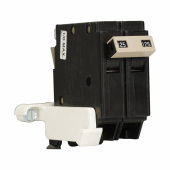
The NEC has requirements for backfed breakers, they must have a way to be "tied down" in the panel. If the panel has no provision to do the tie down , then it's a code violation to back feed it.
I used the main lugs on my panel as well.
 
The NEC has requirements for backfed breakers, they must have a way to be "tied down" in the panel. If the panel has no provision to do the tie down , then it's a code violation to back feed it.
I used the main lugs on my panel as well.
Can you elaborate on this, please?. What does tied down mean.
 
I am doing mine the same as yours, could you take a pic of it inside your ac panel for me?.
It's a assembly that prevents the breaker from being removed. Residential breakers " stab in" to the panel , commercial breakers bolt in. This is a piece of hardware that "ties" the breaker to the panel. This prevents it from becoming loose or popping off the stab in tabs when you turn it off. It's also know as a breaker retainer, or hold down kit. It's just a long screw and some plastic or metal retainer bar.
 
I will have to look into back-feeding a breaker So you connect the inverters one to each panel lug instead of going through a breaker first?. Any good pictures of this and what are the advantages of doing it either way?. I looked at how Will did his through breakers but then heard a lot of people backfeeding or connecting to the lugs.
 
Last edited:
I will have to look into back-feeding a breaker So you connect the inverters one to each panel lug instead of going through a breaker first?. Any good pictures of this and what are the advantages of doing it either way?. I looked at how Will did his through breakers but then heard a lot of people backfeeding or connecting to the lugs.
I suppose this is not done often then.
 
The AC output wires feed into a 60amp breaker. That breaker is attached (permanently) to the sub panel.

Not sure of the advantage other than you can easily get a smaller amp breaker. Most sub panels have their main lug disconnect at 100amp.
 
Also, I tried the DC disconnect for the PV inputs, but I am pretty sure I was losing some amps in that disconnect, so I went with 1000v 125 amp DC breakers as shown below (and similar to Will's setup). The boxes for the breakers only come with two glands, so I ordered a gland kit from Amazon. I assembled the first box just like Will with two breakers per box and both positive and negative cables going through one medium sized gland. It is a tight fit and you have to bend the cables in the box to align them with the breaker terminals. So on the next box I used eight of the smaller glands that were in the Amazon kit and drilled to holes to line up with the breaker terminals. So much easier to install the cables coming in and out of the PV disconnect box.
Could you give me the link for the breakers, please?. Thanks.
 
Not yet. I did get a text message from Peyton at SS and he is going to call me Monday at 3PM. I did read on this forum where some members with EG4 batteries set the battery type to "user" which is user defined to defeat the dreaded fault 61. I changed the battery type from "EG4" to "user" and left menu items 26,27 and 29 at default for "user" batteries. I also set my dip switches on my batteries to address 02-07. Since the "user" battery change, no more fault 61's. However I find it amusing that a generic "user" setting is less fault prone than the EG4 battery with the EG4 inverter. I was also able to get the alarm sound "off" to stick, so no more beeping. I still do not have any disco lights on when the inverters are on, but I can live with that.
I just set up the EG3500 with an Eg4 battery, and I had to switch to "user" setting also. My utility feed was bypassing the battery straight to the load, even when the battery was fully charged. totally defeating the purpose for solar. Ialso have NO alarm sound at any alarm setting. I have a feeling this is going back. SS is working on a firmware fix. Because of the "user" setting, the inverter can't tell me the state of charge on the battery, which sucks. And on top of that, the Solarever 370 watt panels, I bought new from them, are only delivering about 330 watts in full sun. Ok, that's my bitch for the week!
 
And on top of that, the Solarever 370 watt panels, I bought new from them, are only delivering about 330 watts in full sun. Ok, that's my bitch for the week!
90% STC rating is quite good for the hot weather these days...
 
I just set up the EG3500 with an Eg4 battery, and I had to switch to "user" setting also. My utility feed was bypassing the battery straight to the load, even when the battery was fully charged. totally defeating the purpose for solar. Ialso have NO alarm sound at any alarm setting. I have a feeling this is going back. SS is working on a firmware fix. Because of the "user" setting, the inverter can't tell me the state of charge on the battery, which sucks. And on top of that, the Solarever 370 watt panels, I bought new from them, are only delivering about 330 watts in full sun. Ok, that's my bitch for the week!
In looking at your post, I think I might be able to help. First question would be, what do you have programmed for setting #1? If you switch that setting to SBU, it will not use your utility power until the batteries fall below your settings. The EG4 setting in setting #5 will give you the comms you are looking for. If you are having communication issues and getting error 61 I will add some troubleshooting steps below that should fix this issue. Let me know if any of this helps or not.


  1. Ensure that the host battery has the correct dip switch setting. If you have to change this setting, power cycle the battery. (Lifepower4 = down, down, down, down / EG4-LL = down, down, down, up)
  2. All other batteries must have non matching dip switch settings.
  3. Use the provided communications cable to connect the host battery to the host inverter. Then use the short patch communications cable to interconnect the remaining batteries.
  4. Set the host inverter program setting 05 to EG4. If there are slave inverters, set them to USE.
  5. Go back to the main display screen. It may take a minute for the system to recognize the change. If the status does not change, Reset the system.
After three wweeks, I finally got my EG4 3500 inverter to work right. I overloaded it accidently and that seemed to shock it into rythm. Now my utility only comes on when the battery falls below 30%.
The warning beeper is still not audible. Is there a volume control for it? Thanks for your help.
 
Also, I tried the DC disconnect for the PV inputs, but I am pretty sure I was losing some amps in that disconnect, so I went with 1000v 125 amp DC breakers as shown below (and similar to Will's setup). The boxes for the breakers only come with two glands, so I ordered a gland kit from Amazon. I assembled the first box just like Will with two breakers per box and both positive and negative cables going through one medium sized gland. It is a tight fit and you have to bend the cables in the box to align them with the breaker terminals. So on the next box I used eight of the smaller glands that were in the Amazon kit and drilled to holes to line up with the breaker terminals. So much easier to install the cables coming in and out of the PV disconnect box.
I'm building the same system you have basically. Inverters still on order. Can you point me to the PV disconnect box you have on the right (in your picture) ? Also can you give me a link for the gland kit you mentioned ? Thank and your system looks great.
 
After three wweeks, I finally got my EG4 3500 inverter to work right. I overloaded it accidently and that seemed to shock it into rythm. Now my utility only comes on when the battery falls below 30%.
The warning beeper is still not audible. Is there a volume control for it? Thanks for your help.
LOL "shock it into rhythm"
 
My first post and many thanks to Will for starting me on my Solar experience. Based on Will's youtube EG4 48v offgrid build video, I embarked on building a duplicate. I have ZERO experience with DC and solar, but am pretty fair with AC installations. So I purchased two EG4 6500 EX's and wired them in parallel with six EG4 48v 100ah batteries. Everything is working pretty well since I got 1335 watts of solar panel going to each PV1 on each inverter. Batteries are charging well and I have 240v at the main load box. However I do have three issues I cannot resolve.
1. I am getting fault code 61 intermittently both in standby and "on" mode. I can make it go away for a while by switching unit back and forth between stand by and "on". No alarm for an hour or two and then the dreaded beeping. I have battery setting to "EG4", and I have RS485 cables attached from inverters to batteries. Cable from inverter 2P1 is attached to top battery and cable from inverter 2P2 is attached to bottom battery. The RS485 cables that attach between each battery are not installed yet as they were out of stock at Signature Solar when I picked up order, but I am picking up those cables tomorrow along with 36 more solar panels. I read the thread on this forum on assigning battery type to "user" and then defining menu items 26,27, and 29, but darn it these are EG4 inverters and EG4 batteries and they should work together with out any fault codes, lights or beeping.
2. Item 18 on the menu is "Alam control" to turn beeping on or off. System will let me access item 18, system will let me select "off", but system will not save the off selection. I have attempted to select "off" in standby and "on" mode and inverter will default back to "on" for the alarm. I will probably put the alarm to on later, but would like it off for right now.
3. Early in my install, when I would turn the inverters "on" the light bar would run through a sequence of lights and end up with a blue light illuminated all the time. Now, I get no start up light show and the light bar is dark when the inverter is on and working. I do not know what I did to disable the light show.

Long winded questions for a first post, but any help the members can give me would be greatly appreciated. BTW, I placed a tech support call to SS (signature solar) last week and left a message- no call back as of today on that one. Called 3 times today and got kicked out of the que while waiting, finally left another message today-no call back yet. Sent tech support message through their website today-no answer as of yet, so I am seeking help from forum members.

I am approaching this solar adventure as a hobby, because there is no way I can re-coup the $$$ I have spent thus far, and I would have NEVER attempted such a project with out Will's video guidance. I thank him for giving an old guy a new learning experience and having a great time generating energy from the sun.
Cheers!!!
Hey Tash,
Did you ever figure out what was happening with the LEDs? I may have run into the same issue here. I'm running the inverter but they are not on.
 
Talked to Peyton at SS today. He said SS was still fighting the fault 61 issue while using battery code "EG4". He said it was either a cable issue or firmware issue. He said once a fix is found all users will be updated. In the mean time, the fix is to set battery code as "user" and adjust menu items 26,27 and 29 as needed. I also discussed the PV input display with Peyton. I was under the assumption that I could monitor my PV arrays output on the inverter screens. Apparently that is not the case. I have observed that the system will only display the amount of watts it currently needs to handle the current loads. So for instance if I have two arrays PV1 and PV2 wired to one inverter and lets say PV1 has 800w and PV2 has 3700 watts and the only load on the inverter is 1200 watts for battery charging. If I turn on PV1 first then turn on PV2 second, the display will show 800w for PV1, but only 400w for PV2. If I turn on PV2 first and then PV1, the display will show 1200w for PV2 and 0w for PV1. If I put on outside loads of course the values for both PV's will jump up, but I only get to view the "throttled" watts that the inverter "needs" not what the arrays are generating. This makes array trouble shooting more difficult. I wish the inverter would should total PV wattage available for the inverter in addition to the "throttled" wattage. Looking for a digital meter to put between the array and disconnect to show me total array wattage. If anybody has any ideas?
Looking for a digital meter to put between the array and disconnect to show me total array wattage. If anybody has any ideas? Have you found a meter for this yet?. I would also like to read true wattage from the panels coming in.
 
Back
Top