Thanks for the input. I have no problem using the grid input for the generator as I have no potential for grid power. I was already planning on using an in dryer generator as that was suggested in the Mpp solar generator literature. With this set up do you think I will have any other issues to deal with? I don’t need to do anything fancy….just power the house! I had heard that the manual might have the wiring for parallel set up wrong but haven’t been able to confirm that. I emailed Ian but haven’t heard back (I’m sure he’s quite busy).


You are using an out of date browser. It may not display this or other websites correctly.
You should upgrade or use an alternative browser.
You should upgrade or use an alternative browser.
New All in One: MPP LVX6048WP (UL certified)
- Thread starter topnotchit
- Start date
As far as I know, wiring in parallel is not a problem. I used breakers and power distribution blocks to streamline my wiring. Let me know if you have any specific questions. I used the power distribution blocks to create an "ac combiner box" of sorts, and the breaker is there so that electric doesn't run back into the inverter that is off. That explanation probably doesn't make much sense, but I can put up pictures and explain my setup if you want clarification.Thanks for the input. I have no problem using the grid input for the generator as I have no potential for grid power. I was already planning on using an in dryer generator as that was suggested in the Mpp solar generator literature. With this set up do you think I will have any other issues to deal with? I don’t need to do anything fancy….just power the house! I had heard that the manual might have the wiring for parallel set up wrong but haven’t been able to confirm that. I emailed Ian but haven’t heard back (I’m sure he’s quite busy).
jasonhc73
Cat herder, and dog toy tosser.
I'm on two LV6548s still. I will be going to 3 LVX6048s, assuming the GEN Input is safe to use as described.Any schematic of your setup? Would love to check it out.
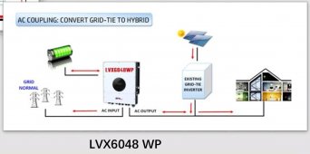
Have you/anybody been able to confirm that the “Gen Input” will work with an AC Coupled PV setup with the latest version of the hardware, instead of blowing up?
Ok, I'm at work (work nights) Will get some pictures up tomorrow.Thanks. I would love to see your pictures!
Are you going to the regular LVX6048's or the LVX6048WP's. If it's the WP's the problem was only with the "first batch" that were released in early april this year. Subsequent releases do not have that problem, as far as I know.I'm on two LV6548s still. I will be going to 3 LVX6048s, assuming the GEN Input is safe to use as described.
Have you/anybody been able to confirm that the “Gen Input” will work with an AC Coupled PV setup with the latest version of the hardware, instead of blowing up?
houseofancients
Solar Wizard
contact ian, he should be able to verify with 100% certaincyI'm on two LV6548s still. I will be going to 3 LVX6048s, assuming the GEN Input is safe to use as described.
Have you/anybody been able to confirm that the “Gen Input” will work with an AC Coupled PV setup with the latest version of the hardware, instead of blowing up?
Thanks. I would love to see your pictures!

Click on picture for larger view
PDB= Power Distribution Block
One PDB Joins 2 black hots one from each inverter
One PDB Joins 2 Red hots one from each inverter
One PDB Joins 2 white Neutrals one from each inverter
One PDB Joins 2 green Grounds one from each inverter
Before the getting to the PDB each inverter output goes to breakers as follows:
Red, Black, and White to 3 pole 25A breaker, green to 0.5A single pole breaker
Last edited:
Thanks for posting the photo. It is very helpful! Nice neat set up. Ian had said that the 6048wps could be paralleled the same way as the 6048s as he demonstrates on his video. It seems you have added the PDBs as a means to clean up the wiring. I am not sure what my installer wants to do with wiring but what you have is tidy and simple to understand. Some equipment is harder to get in Mexico.
Any chance you could take a photo of how you wired the parallel communication wires (not the power wires) using the wiring kit that comes with the 6048wps? Thanks again so much for taking the time to post your photos and comments. I will pay it forward and post my system when I have it up and running successfully.
Any chance you could take a photo of how you wired the parallel communication wires (not the power wires) using the wiring kit that comes with the 6048wps? Thanks again so much for taking the time to post your photos and comments. I will pay it forward and post my system when I have it up and running successfully.
jasonhc73
Cat herder, and dog toy tosser.
Sanwizard
Solar Wizard
- Joined
- Feb 2, 2021
- Messages
- 2,718
That does not make sense. The manual says DO NOT connect AC output to the grid.I just reread on MPP-SOLAR site. Using the generator input will not backfeed the grid.
So, to backfeed the grid with an AC coupled setup, put the AC coupled setup anywhere on the loads side.
CAUTION: Do NOT connect the utility to “AC Output Connector (Load connector)”. CAUTION: Be sure to connect L terminal of load to L terminal of “AC Output Connector(Load connector)” and N terminal of load to N terminal of “AC Output Connector(Load connector)”. The G terminal of “AC Output Connector” is connected to grounding of the load. Do NOT mis-connect.
jasonhc73
Cat herder, and dog toy tosser.
I know, but you see the picture just like I do.That does not make sense. The manual says DO NOT connect AC output to the grid.
CAUTION: Do NOT connect the utility to “AC Output Connector (Load connector)”. CAUTION: Be sure to connect L terminal of load to L terminal of “AC Output Connector(Load connector)” and N terminal of load to N terminal of “AC Output Connector(Load connector)”. The G terminal of “AC Output Connector” is connected to grounding of the load. Do NOT mis-connect.
I'm emailing Li now to get more of an answer. Ivan hasn't replied either.
Notice on Page 4, that the AC Grid connectors don't say "input or output".
This is incredibly confusing since they say do not use the gen input to AC Couple.

Last edited:
jasonhc73
Cat herder, and dog toy tosser.
Of course, this is all moot if I just remove my AC coupled inverter and put the PV into the LVX6048WP. ?I know, but you see the picture just like I do.
I'm emailing Li now to get more of an answer. Ivan hasn't replied either.
Notice on Page 4, that the AC Grid connectors don't say "input or output".
This is incredibly confusing since they say do not use the gen input to AC Couple.
View attachment 114651

Sanwizard
Solar Wizard
- Joined
- Feb 2, 2021
- Messages
- 2,718
Exactly.Of course, this is all moot if I just remove my AC coupled inverter and put the PV into the LVX6048WP. ?
Thanks for posting the photo. It is very helpful! Nice neat set up. Ian had said that the 6048wps could be paralleled the same way as the 6048s as he demonstrates on his video. It seems you have added the PDBs as a means to clean up the wiring. I am not sure what my installer wants to do with wiring but what you have is tidy and simple to understand. Some equipment is harder to get in Mexico.
Any chance you could take a photo of how you wired the parallel communication wires (not the power wires) using the wiring kit that comes with the 6048wps? Thanks again so much for taking the time to post your photos and comments. I will pay it forward and post my system when I have it up and running successfully.

Not sure if this is what you're asking for, but there's not much to these. You just have to make sure the wires are in the same order on one inverter as it is on the other.
Sanwizard
Solar Wizard
- Joined
- Feb 2, 2021
- Messages
- 2,718
Does anyone know why the LVX8048WP manual page 11 shows PV connected to MPPT1 always with more panels than MPPT2? Example, for 430W panels, it shows 12 panels in series for MPPT1, and 6 panels for MPPT2. Then in the same chart, it shows maximums as only 5 panels per input?View attachment 114981
Not sure if this is what you're asking for, but there's not much to these. You just have to make sure the wires are in the same order on one inverter as it is on the other.
The chart shows 579V for mppt1, and 289V for MPPT2. Very confusing, since the inverter is supposedly rated for 600V, but MPPT1 and MPPT2 combined are over 800V.
I'm really not sure why that is, but my guess is that it is just some mistranlation/confusion by whoever wrote it. I intend to keep the combined total of my connected panel VOC's at 480 or below. To account for voltage jump in cold weather. I wouldn't go any higher and will not trust the information in the manual.Does anyone know why the LVX8048WP manual page 11 shows PV connected to MPPT1 always with more panels than MPPT2? Example, for 430W panels, it shows 12 panels in series for MPPT1, and 6 panels for MPPT2. Then in the same chart, it shows maximums as only 5 panels per input?
The chart shows 579V for mppt1, and 289V for MPPT2. Very confusing, since the inverter is supposedly rated for 600V, but MPPT1 and MPPT2 combined are over 800V.
Maybe someone in here can help. I am currently looking into this inverter for the purpose of charging batteries with the AC-in, and powering some critical loads with the AC-out (both while grid is up and down).
From communications with MPP, they have essentially said three main things:
1) neutral is maintained when passing through grid
2) neutral floats when grid is down
3) could do a neutral-ground bond in the critical load panel
I keep coming back to:
a) there is either two N-G bonds if 3 occurs (main panel, critical load panel, linked through the inverter) or
b) no N-G for the critical load panel when inverter switches to battery (the neutral floats, as per communications with MPP)
( c) possible ground loops are well depending in solutions)
I realize I may be missing something fundamental here, which is why I am asking from people that may have done it.
Thanks
Bleedingblue
Solar Enthusiast
- Joined
- May 12, 2020
- Messages
- 558
I think the neutral ground hook up is the most asked about topic about these type of units. And is complicated
That is what I have gathered.there must be someone that has managed to do it properly though.I think the neutral ground hook up is the most asked about topic about these type of units. And is complicated
I'd rather not have a setup where AC-in charges it. Then turn off AC-in. Then connect AC-out. Which seems to be a 'solution' but not necessarily what I am looking for since that essentially makes it a generator instead of something that can be used to transfer some loads (I think I could live with that but there must be a more elegant solution).
Similar threads
- Replies
- 7
- Views
- 547
- Replies
- 7
- Views
- 750
- Replies
- 34
- Views
- 2K
- Replies
- 10
- Views
- 506