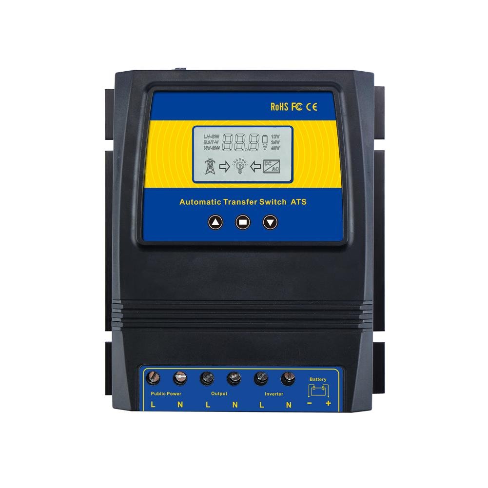
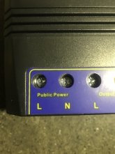
Based on this diagram:

-'Public Power' would wire to the source power from the power company (maybe you have a designated breaker allocated for providing this power from your main breaker panel).
-'Output' would go to your 'critical loads' auxiliary breaker panel (which feeds all your critical loads household circuits).
-'Inverter' would connect to your inverter AC output terminals.
-Battery would go to your inverter's power source battery bank to provide the sense voltage, to trigger the ATS switchover logic.
L is the 'hot' or black wire (in USA anyways).
N is the return or white wire (in USA anyways).
Make sure your critical loads panel loads don't exceed the amps/watts capacity of this ATS.
It looks like, based on the specs below that the 5500w unit doesn't support 240v so you can only tie into one leg of your main breaker panel to get 120v (one hot, and neutral). The 11000w unit looks like it supports 240v, so it could tie into both legs of the main breaker panel (two hots, no neutral).
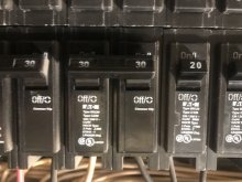
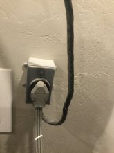
You would need to wire public power to a breaker in order to allow it to pull the 50a rating, an outlet can only support usually 15a unless it is a 20a outlet, it would only allow 20a max, you need 50a connection to support full rating of this ATS.
If you haven't seen all the specs, I found them here in the different pictures posted for the unit:
The ATS controller will switch to grid power when the voltage of batteries is lower than the voltage transfer setpoints,and it will switch back to battery power itself when the voltage of batteries is higher than recovery setpoints.

www.moeshouse.com