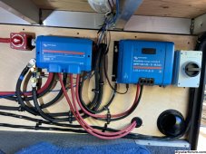
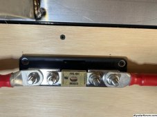
Hello, new to the forum. I just installed a multiplus II 12 volt into a RV With 5 battle born batteries. Everything went pretty good, but the short 4/0 wire between the fuse block and shutoff switch of the hot side is getting really hot when i run the ac off the batteries (AC and frig pulling about 1800 wats showing on the monitor). I’m showing up to 165 degrees Fahrenheit then I shut it down. It was getting hotter on the fuse side I believe, so I made a new 5 inch wire, now it seems to be getting hotter on the shut off switch side. I turned it off after it hit 160%F This time. I made my own cables, I have a quality crimper. Any help would be appreciated. The switch and fuse block and 400ANL fuse is blue sea systems brand, they are supposed to be good. I called battle born where I got most the stuff from and all they say is something is causing resistance.


You are using an out of date browser. It may not display this or other websites correctly.
You should upgrade or use an alternative browser.
You should upgrade or use an alternative browser.
New multi plus II install but main redpower wires getting too hot.
- Thread starter therabbit
- Start date
Samsonite801
Solar Wizard
- Joined
- Oct 15, 2020
- Messages
- 2,994
If it were me, I would run it hard, then while it's hot and running hard, do a voltage drop test at various points, this is where you put the + lead of voltmeter on one end of a cable, and put the - of the voltmeter lead on the same cable, but at the other end of it, it could for example show .8v (just an example), that means that there is resistance in that cable. You can use this trick with any part of the circuit (section that gets hot), in between the test leads, since the resistance means it is like a load, so it will register a voltage drop in between it (like a load in series)... Voltmeter shows the differential in voltage seen across the measurement point in between.
Let me know if that makes sense (the way I articulated it), or if I need to try and explain it differently... I learned voltage drop testing as a professional mechanic many years ago. You can test voltage drop across any parts of the circuit (measuring components in series), like switches, connectors, cables, etc.. Anything with resistance across it will show up as a voltage, effectively reducing that measured amount of voltage from reaching the end where the real load is connected at.
If there is no voltage drop (a small amount only), it might only show in the mV between each point, and you can add them all up in the circuit and all the small numbers add up to the sum of total circuit voltage drop arriving at the intended load.
Last edited:
I used a Blue Seas Class T fuse and fuse holder in that position. I have no hot spots and I pull similar watts, also on a 12 volt system. I charged my EV for three hours as a test.
Are your cable crimps solid? Try to pull the lug off the cable. Try really hard!
Are the connecting surfaces clean and free of corrosion, dirt, etc.?
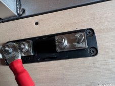
Can you provide a closeup of the fuse holder? Make sure there is nothing between the cable lug and the fuse holder surface.
Are your cable crimps solid? Try to pull the lug off the cable. Try really hard!
Are the connecting surfaces clean and free of corrosion, dirt, etc.?
Can you provide a closeup of the fuse holder? Make sure there is nothing between the cable lug and the fuse holder surface.
I’m not sure if I did the voltage drop test right, but the shut off switch was up to 0.060, the highest of all. The fuse was up to 0.030 alone, the short wire was .002. All together was hitting 0.10. Is that allot?
The littler fuse on the distributor for the wire going to the inverter was 0.030, that wire was heating up also.
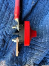
I took the switch off and I noticed it was wired backwards according to the underside words, input/output, but I don’t see how that matters on just a cut off switch.
I took off the switch and bypassed the fuse with a jumper wire, haven’t tested it yet, getting ready to test it now. The distributor has fuses so it should be safe for a quick test to see if it heats up.
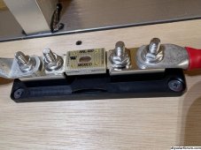
I also don’t like the way the fuse holder has a cloudy surface where the wire bolts to, this is a brand new fuse holder, everything is new.
The littler fuse on the distributor for the wire going to the inverter was 0.030, that wire was heating up also.
I took the switch off and I noticed it was wired backwards according to the underside words, input/output, but I don’t see how that matters on just a cut off switch.
I took off the switch and bypassed the fuse with a jumper wire, haven’t tested it yet, getting ready to test it now. The distributor has fuses so it should be safe for a quick test to see if it heats up.
I also don’t like the way the fuse holder has a cloudy surface where the wire bolts to, this is a brand new fuse holder, everything is new.
Attachments
-
 122E1EE2-5B89-4023-A33E-1F3ECD78FD47.jpeg229.3 KB · Views: 35
 -
 72BB50B2-7526-4390-B743-68FA69FABA3A.jpeg242.8 KB · Views: 32
 -
 E795D867-4D95-463B-9407-67B895997D78.jpeg223.7 KB · Views: 30
 -
 73DA676B-9E82-437A-B9CA-7A59DBEBBEA7.jpeg244.1 KB · Views: 30
 -
 46F0F435-1249-4EAB-9CD9-21843ED0BCCA.jpeg279.9 KB · Views: 33
 -
 143B2668-F848-4E8B-9D0D-2427AC23D2CD.jpeg334.4 KB · Views: 35
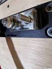
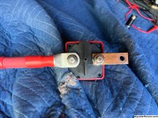
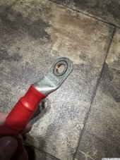
The right side of the short wire at the shut off switch is 10 degrees hotter then the left side of the short wire and the fuse holder and other stuff. That left side of the switch seems to be the hottest as the temperature climbs. My temp tool isn’t reading the right side of the switch as well because it’s shiny, but to the touch it’s not as hot as the left side (output side because I have it backwards) it seemed to be the starting point of the heat.
the only other issue is that’s the only wire lug I didn’t have the right hole for, I had to drill it out to 3/8s, but I don’t see how that could be it. But it’s where it’s getting hottest at. You see the copper in the hole because I drilled it, it’s not tinned there anymore.
the only other issue is that’s the only wire lug I didn’t have the right hole for, I had to drill it out to 3/8s, but I don’t see how that could be it. But it’s where it’s getting hottest at. You see the copper in the hole because I drilled it, it’s not tinned there anymore.
Attachments
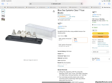
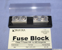
What amp do you use? Like this one?I used a Blue Seas Class T fuse and fuse holder in that position
Attachments
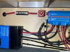
I put this jumper wire on and eliminated the fuse and switch and the wires didn’t go over 110 degrees, felt more normal.
I put the switch back on, this time the right way and it’s heating back up. Already past 140, maybe this switch is bad. Any ideas or help would be appreciated, thanks.
I put the switch back on, this time the right way and it’s heating back up. Already past 140, maybe this switch is bad. Any ideas or help would be appreciated, thanks.
Attachments
Samsonite801
Solar Wizard
- Joined
- Oct 15, 2020
- Messages
- 2,994
I put this jumper wire on and eliminated the fuse and switch and the wires didn’t go over 110 degrees, felt more normal.
I put the switch back on, this time the right way and it’s heating back up. Already past 140, maybe this switch is bad. Any ideas or help would be appreciated, thanks.
First off, I'd use a Class-T fuse, they are a lot thicker on the contact lugs..
Have you checked the max current with your DC amp-clamp probe and compare that number with an NEC ampacity chart to see? Your cable should have a max temp rating on it.
NEC Ampacity chart:
I know my charge controller cables get pretty hot when both chargers are pegging at 100a each, but it is within spec of the wire and expected due to the gauge I'm running there (which is the largest that my charge controller can accept on the lugs), so I leave it.
But the last time I saw this issue (on a neighbor's system) of really hot heat problem on only one conductor (in my case a positive lead), it was right by a cheesy Amazon 4-bolt bus bar, and it was getting so hot (melted the plastic holder the bus bar was molded into) it was transferring the heat all the way down the cable (was a good high quality 4/0 cable too), but the heat was originating from the cheesy bus bar.
I'm thinking maybe that cheap fuse is creating the heat and transferring up your cable, thus why I'd prefer a Class-T fuse with the heavy fuse holder there.
Last edited:
I’m going to order one, what size do you run?. That fuse is blue sea. Apparently the T-fuses where hard to get for a while, so theses where the next option. looks like they are available now.I'm thinking maybe that cheap fuse is creating the heat and transferring up your cable, thus why I'd prefer a Class-T fuse with the heavy fuse holder there.
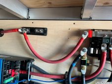
this is a Victron distribution box/buss bar, it should be good.
I’ve been tracing the heat source, it seems like it’s the switch (10% hotter then anything else). I guess I’ll order another one. It ran at 110 with the bypass wire. That’s good I think.
but the 4/0 to the inverter is getting hot at its 300A fuse. 140 degrees at the fuse, it’s a Victron fuse. Maybe I need a 400A.
I don’t have the clamp voltage checker.
I also don’t exactly understand what size fuses I should run ?.
my wire is 4/0 Temco easy flex welding cable, it’s not cheap, it’s -50% C to +105% C (221% Fahrenheit) the inverter wire now is hitting 140%F, so I’m in spec with that I guess. But the 165 at the shut off switch is still in spec but just seems to hot.
it would be nice to see what other systems actually run, wire hot wise under a ac load. Thanks for the input.
Samsonite801
Solar Wizard
- Joined
- Oct 15, 2020
- Messages
- 2,994
I’m going to order one, what size do you run?. That fuse is blue sea. Apparently the T-fuses where hard to get for a while, so theses where the next option. looks like they are available now.
this is a Victron distribution box/buss bar, it should be good.
I’ve been tracing the heat source, it seems like it’s the switch (10% hotter then anything else). I guess I’ll order another one. It ran at 110 with the bypass wire. That’s good I think.
but the 4/0 to the inverter is getting hot at its 300A fuse. 140 degrees at the fuse, it’s a Victron fuse. Maybe I need a 400A.
I don’t have the clamp voltage checker.
I also don’t exactly understand what size fuses I should run ?.
my wire is 4/0 Temco easy flex welding cable, it’s not cheap, it’s -50% C to +105% C (221% Fahrenheit) the inverter wire now is hitting 140%F, so I’m in spec with that I guess. But the 165 at the shut off switch is still in spec but just seems to hot.
it would be nice to see what other systems actually run, wire hot wise under a ac load. Thanks for the input.
Well when I run my AC in the motorhome for hours and hours on end, my cables get decently hot too (12v systems run the highest current to get the same watts). I run a Magnum 2800w inverter, and use two 2/0 wires running parallel from middle basement to backend engine compartment, and have the old Blue Sea Systems 5002 fuseholder which I believe is discontinued now (where I have a 350a Class-T Littlefuse). I liked that 5002 fuseholder best because it had 3/8" diameter bolt mounts in it, with the big heavy block lugs on it. Now I think they replaced it with 5502 which is cheesier to me, thinner block lugs on it. Might just make my own next time if I need another one for a high current 12v application again.
With 12v, going up to 3000w-ish, no doubt things get hotter when running close to limits, I have two 250|100 charge controllers, those are baking every day at full Sun, the wires going out of them to the bus bars are hot, the wires going to the inverter are hot, the inverter is baking (when AC is running inside).
One day in August on 100° F day, I checked the temp of my inverter on the remote inverter screen, and found I was only 4° F from hitting max temp spec limit (fans were screaming), so I wound up putting a box fan outside a few feet away blowing into the inverter compartment to help the heat accumulation in the compartment (I always leave the compartment door open when AC is running), blowing cooler outside air better into the compartment.
I also keep a fan running all day blowing against my charge controllers as well. They are still all within spec, but they sure feel hot when pegged at 100a each for hours.
I am not saying whether you have a problem or not, but just suggesting that some of that heat might be normal, 250a-350a is a lot of current.
Since you have the Multiplus II, another option is to try using 2 inverters in parallel (stacked), so it splits the load and the heat will distribute better as well, each device and cable run will produce lower temperature.
Oh and on fuse size, remember that the fuse is always to protect the cable from meltdown, but also large enough to meet the demand of the inverter, so on mine, in my manual (for Magnum anyways), they publish a max current draw on DC side, so I made my fuse a bit bigger, but small enough as I could get away with to protect the cable (mine is essentially 4/0 since I have two 2/0 runs around 14ft, going to fuseholder then a 5ft chunk of 4/0 going to the inverter from the fuseholder), so I chose 350a Class-T fuse for mine, always holds the load, right up to inverter overload shutdown.
Last edited:

Samsonite801
Solar Wizard
- Joined
- Oct 15, 2020
- Messages
- 2,994
I see washers.
In some pictures they are on top of the fuses and crimp terminals, which is OK.
In some pictures I can't see them.
If between terminal and busbar, that's not OK, high resistance.
View attachment 171832
Yeah those pictures above kind of look like the newer Blue Sea Systems 5502 (which replaced the original 5002), the new ones have way thin lug mounts on them, the older 5002 were great, they were like 1" x 1"x 2" long lug mounts on each side of fuse, I think better for pushing lots of current through them, wish they still sold those older ones.
Example of the older 5002 fuseholder:

Attachments
Last edited:
Samsonite801
Solar Wizard
- Joined
- Oct 15, 2020
- Messages
- 2,994
All together was hitting 0.10. Is that allot?
It depends a lot on the current, there is some math one can do to figure out more precisely. Generally in a circuit we would like to keep overall circuit voltage drop sum lower than 3% according to NEC (in the case when they refer about AC power to feeders and branches). However, I like to shoot for the lowest voltage drop I can reasonably afford, for better performance and even less heat generation..
Example may be if total sum drop in the circuit is .1v at 250a, that = 25w of wasted power (heat) in question there. Also a .1v drop is not as big of a deal when circuit voltage is say 250v or 500v, but at 12v, it will have more of an impact. Heat dissipation is a factor too, since an insulated wire blankets in more heat, so it tends to accumulate heat energy where it gets hotter and hotter, up to it's point of saturation and dissipation where it peaks and is transferring continuously the flow of heat to the air around it.
In automotive circuits I would typically troubleshoot, I wouldn't assume .1v was much to worry about, because most of these circuits are not pushing high current. High current blows the numbers up much higher though, means higher watt losses.
Also, when you were testing for example, the fuseholder, were you doing it on the fuseholder lugs themselves, or probing on the cables outside of the connectors? In other words to capture the reading all around including the ring terminals and crimps around it.
More reading in case you're curious:
How much heat is generated
I was wondering if there is a way to calculate how much heat current flow generate. For example: How much heat is generated by a continuous current flow of 80Amps? Is there a ratio of so many amps will generate so much heat? I am not even sure if this is a valid question.:?
forums.mikeholt.com
Last edited:
I was probing everything, I tried at the holders bolt lugs, then at the cables crimped on lugs, I didn’t push into the wire if that’s what you meant. I checked from the right (out) side of the shut off switch to the input cable lug of the fuse holder, that’s where I got the largest 0.010 Once. I didn’t understand why the volt meter was reading with 3 numbers right of the decimal point, 0.020 and 0.050, but when checking 12 bolts hot to ground it it went back to 0.00, it lost that 3rd number to the right. Did I do the test right? Is that 0.050 the switch did half a volt?Also, when you were testing for example, the fuseholder, were you doing it on the fuseholder lugs themselves, or probing on the cables outside of the connectors? In other words to capture the reading all around including the ring terminals and crimps around it.
Samsonite801
Solar Wizard
- Joined
- Oct 15, 2020
- Messages
- 2,994
I was probing everything, I tried at the holders bolt lugs, then at the cables crimped on lugs, I didn’t push into the wire if that’s what you meant. I checked from the right (out) side of the shut off switch to the input cable lug of the fuse holder, that’s where I got the largest 0.010 Once. I didn’t understand why the volt meter was reading with 3 numbers right of the decimal point, 0.020 and 0.050, but when checking 12 bolts hot to ground it it went back to 0.00, it lost that 3rd number to the right. Did I do the test right? Is that 0.050 the switch did half a volt?
No, the .5v is 1/2 a volt, or 500mA... a lot of these voltmeters start out on auto-scale (auto-ranging) mode, where they detect the volts and scale/range according to it (as seen in where the decimal moves to).
I'm using a 225 amp Class T fuse. I've never pushed my system over 200 amps.
There are polarized circuit breakers but I've never heard of a polarized switch. Maybe it's a thing. I don't know. Your test does seems to narrow the problem down to the switch. If the switch has high resistance then I could see everything downstream from that heating up.
There are polarized circuit breakers but I've never heard of a polarized switch. Maybe it's a thing. I don't know. Your test does seems to narrow the problem down to the switch. If the switch has high resistance then I could see everything downstream from that heating up.
Samsonite801
Solar Wizard
- Joined
- Oct 15, 2020
- Messages
- 2,994
There are polarized circuit breakers but I've never heard of a polarized switch. Maybe it's a thing. I don't know. Your test does seems to narrow the problem down to the switch. If the switch has high resistance then I could see everything downstream from that heating up.
As you probably know already, they could be polarized when voltage rating is higher than a certain amount (don't remember exactly what voltage they consider), but usually polarized switches or breakers have to do with arc extinguishing at higher voltages (as they use polarized magnets to help with breaking the arc), but devices rated for < 60v wouldn't be subject to any polarization rules I would think.
Based on my experience, if the switch may have some sort of a labeled terminal designation, like 'Batt' here 'Load' there, then I would observe it for good measure, but if not labeled I would use either terminal without discretion.
I have my 12 volt blinders on and wasn't thinking about higher voltages. Thanks for the info!
I don’t have room for a second inverter, I barely fit five batteries over the generator. I think I could do another 5 batteries in a different spot, but another inverter would be hard. the batteries are $200 off today (prime day), I was thinking about doing the other 5, but if I can’t make this system stay cool I don’t need more money in it.
I turned this inverter sideways (lack of room) and that makes it harder for the heat to get out apparently, so with all this heat I’m concerned about it’s sideways mounting now. I’m going to put a computer fan on one end and try to push air threw it. Ive installed a 4in blower and ducting to try to move air threw and over the area, but I think I need more. I’ll probably have to open the door when running the ac like mentioned.
I ordered a new switch and the T fuse and holder, I wish they still had the older holders, but blue sea is supposedly a quality outfit so it should be tested to be good. I went with the 400A fuse, perhaps I should have got the 300A fuse. That area ran a nice 110F with no fuse or switch (just bypass wire), that’s tempting to just do it that way. The distributor has fuses in it. But there has to be a way to do it right.
Anyway, maybe the heat is all within spec and ok, I don’t know. I’ll see if I can find heat specs for the inverter and Victron distribution box. Maybe all this heat is why they say it’s better to run 24 or 48V systems. I’m in the desert, so I need to run that ac allot If I go off grid at times. I’m hooking up 6x200W panels this weekend. So I’ll see how that runs I guess.
I don’t see anyone on all the YouTube videos talking about heat. Changinglanes supposedly has the same 12V inverter and they have 3 ac‘s, I don’t get how they can run 3 on a 3000 watt inverter, maybe 2 but not 3.
What percentage loss is 0.010 (old fuse to off switch run) is that 1 volt? I take pain meds for neck and back issues, all this math is hard to put together ?.
Partimewages
Solar Addict
I only believe about half of what I see on Changing Lanes.
Similar threads
- Replies
- 2
- Views
- 197
- Replies
- 17
- Views
- 709
- Replies
- 37
- Views
- 1K
- Replies
- 2
- Views
- 94