diy solar

diy solar

New no battery pure sine wave solar power system with smart switchers.

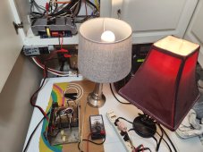
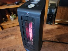
10 AM below freezing outside, running a quartz tube heater at each end of the house ?

Say what you want, I am loving it.?

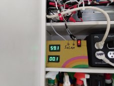
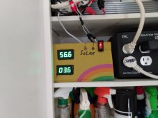
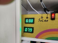
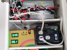
Here is real world what happens when a dark cloud pass in front of the solar PV array (event ended moments ago with return to full sun) running overhead lights and two heaters, everything smoothly shifts down a notch in intensity, most notable was the fan speed of the quartz tube heater, 3.1 amps shifted to the 120 VAC secondary power from the 5.4 amps solar input, remaining that way till the cloud passed and the full load returned to solar bringing everything back up a notch.

Got 4.5 hours of dual solar heaters on a cold partly cloudy day.?

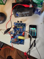
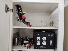
With voltage controlled relay, sun sensor or timer you can control the loads on the system automatically, I have placed two electric heaters for the season at each end of the home just in time for negative winter temperatures to assist with comfort.
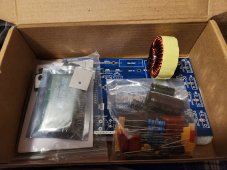
 

Attachments

  • IMG_20221219_100831616.jpg
    IMG_20221219_100831616.jpg
    218.5 KB · Views: 8
Last edited:
What is the voltage at the output of the inverter in full sun compared to in shade with the secondary AC current flowing?

I will attempt to put exact numbers to your question soon, but an educated guess is 15 to 20% in brightness/voltage increase during PV full input especially with 18 PV panels, today was overcast and the system could only run one heater on its lowest setting, over head lights,and cams/monitors.
Still a good solar day all in all.?

Just now have the ability to push the limits on the 18 PV panels, just need a clear full sun day to deliver the highest numbers so far, still expecting voltage sag when heavy loading the boards.

By closely monitoring the output voltage basically keeping it above 98 VAC, we should get some some impressive KWH production numbers in full sun, the CPU can have a full color display, suspect it could be programmed to maintain a voltage like 98 VAC or trip off if voltage drops to 90 VAC or below.
 
Last edited:
Successfully running dual solar heaters, 11 AM up to now the outside temperature has been in the single digits.?

Running two mini split heat pumps off grid power for a 62 degree Fahrenheit indoor temperature.
 

Attachments

  • IMG_20221223_110349709.jpg
    IMG_20221223_110349709.jpg
    170.4 KB · Views: 8
  • IMG_20221223_110431301.jpg
    IMG_20221223_110431301.jpg
    166.8 KB · Views: 8
Mixed news from the past four days of below freezing outside weather with the new power system, today heavy overcast and snow, previous day full sun blue sky, previous two days mostly sunny.
Fortunately had good sun for the three coldest solar days and ran living room quartz heater on it's first setting (1) tube glows bright when the sun is shining, also running overhead lights,fans,cams, monitors and in full sun it would run a second heater on it's lowest setting in the back hallway.
Bridged two 30 minute rolling blackouts glowing orange heater and overhead lights was very comforting.

Now the bad news no matter what I tried accessing more than 65% of the raw PV power was not possible with out a DC/AC voltage crash.
When the weather improves going to special to test all 18 panels in series for a raw power output test.

More soon .

Solar panels have cleared themselves from about 2 inches of snow got the PV power back around 11 AM ?
 
Last edited:
Have been studying this forum and other online sources about MPPT.

Simpley put it is DC to DC down converter that maintains the highest PV voltage possible while outputting a lower voltage and higher amperage to the load.

What needs to be done is use all eighteen 12 VDC PV panels in series to produce the required 180 VDC output to the pure sine power boards, in two of the videos I watched 180 VDC was mentioned and 18 PV panels but no mention of the equipment you might use to have this setup.

The power board runs efficient and only gets into trouble once the PV 180 VDC starts to fall off, in full sun with no power management (MPPT) at 65% to optimal 70% of full PV load is all that is possible with out getting into unacceptably low AC output voltage.

I am happy with the low light PV power production and 65% total full sun PV efficiency, yes I wish the numbers were a bit higher but this small power system has preformed wonderfully during the past frozen week.

I have a self imposed rule to keep this whole project under 200 volts, It will be up to others to explore higher voltages and anything over 15 amps.?

As we get away from winter and back to longer solar days I will shift the load of the new power system to fridges, freezer and mini split testing.
 
Last edited:
Have moved everything I can to a new 5G android phone, should mean better photos, and communication.

The CPUs that were ordered for the 2000 watt pure sine board have been delayed and awaiting incoming US customs, original delivery date Dec 21st.

Upon parts arrival and repair of the 2000 watt power board I plan to use the slim silver inverter case to contain the 2000 watt pure sine board and currently in use 1000 watt board. The entire old system and new systems will be simplified and updated, prep for more solar panels and about half the old low voltage system,charge controllers and wiring will be removed ?
Some of the old MPPT equipment will be tested in an effort to increase PV efficiency 20 to 30 percent on the newest systems.
The older system is a 3000 watt pure sine 12 volt deep cycle battery that blends in grid support, runs living room,EV car charger and supports the CPU/fans/ISO secondary transformer on the new systems.
Definitely on track to meet or exceed my goals with the new power system, Looking forward to a bright summer ?
 
Last edited:
Super interesting results from first MPPT sourced pure sine power board testing.

First noticed you can power the boards at 18 VDC and still get a sine wave output during FET replacement testing and building up the combo unit (2000+1000 combo boards)
I have a large transformer 120 to 14 VAC that was used for a DC power supply back in the day to run CB radios and 8 track tape decks and other car units.

Today I hooked up the CPU to 18 VDC (9 volt batteries X2) on a new power board, The power board input connected to MPPT sourced 12 VDC, bypassed the power board input resistors and connected the power board output to the transformers 14 volt side/ on the 120 volt side I connected a 8 watt LED 120 VAC lamp and "O" scope.

To my surprise and amazement the power board and light ran smoothly, big opertunity here to use 12/24/48 DC sourced MPPT power, the downside is a custom output ISO transformer, Transformer is what is needed to give a proper neutral and ground to the output power and correctly match the output voltage 12-24-48-etc.

With having the proper transformer for 12-14 volt range over the next few weeks lots of testing ahead to test the limits of a 12 volt MPPT driven power board.

No matter what this pure sine power board and transformer are destined to be mounted into a portable case for power production/off grid uses.?
 
Last edited:
The power board FETs work better at higher input DC voltage, first test suggested 24 or 48+ volts input to actually run something more than a handful of LED light bulbs.

What may come from this testing is a way to channel more secondary 120 VDC power through the power board FETs, All power board DC input travel through a bank of four to six parallel resistors, since the board is designed to run at 380 VDC bypassing the resistors for 120 to 180 VDC operation may deliver higher output AC voltages. Especially with the 2000 watt board, more testing over the next few days is needed to see if I can substantially increase the output.

More to come.
 
Last edited:
Something interesting max power about 250 watts,100 VAC pure sine, 12 VDC MPPT sourced input to a 1000 watt pure sine board also the CPU and fan. Input resistors bypassed on power board.

Added 15 turns to the transformer to boost output voltage needs more but that's all I could fit with out spending money, duct work and fan for cooling heat sinks.
Needs a nice case with a handle to run lights, phone chargers and more from 12 volts DC or higher.

Currently under going long term test run.
?
Would probably run good with three standard 12VDC solar panels in full sun with no battery or any 12-16 VDC power source.

This testing is providing data on getting the most power through the power board FETs, although I don't expect anything big one thing jumps out of the data, if the mail will ever deliver the CPUs and I can fix the 2000 watt pure sine board it will handle double the efficiency/current of what I am getting now 4 FETs VS 8 FETs.
Expect better efficiency numbers soon for secondary power support and PV power production, something I already like is going to get a step better.
 

Attachments

  • 20230104_194238.jpg
    20230104_194238.jpg
    262.2 KB · Views: 7
Last edited:
More information in the previous post to improve understanding of the proposed changes in the main project.

To substantially increase overall efficiency and performance of the new pure sine power system recommend the 8 FETs 2000 watts version of the power board and bypassing the power board input resistors for 120-180 VDC operation, this configuration has not been fully tested yet but I see no reason it should not work to make the system better in every way. ?

The FETs are the gateway between PV and the secondary power sources you want to things you need to run, the more FETs the more efficient the power transfer, due to a series of mistakes I have been limited to 4 FETs per powerboard for months now, need 2-1000 watt pure sine kits to build the 8 FET 2000 watt board you really need.
 
Last edited:
Looks slightly different than anything I have purchased before, last 2000 watt pure sine kit 8 FETs listed on Ebay, expect delivery Feb 15, have two different PCBs to choose from one with a really nice pure sine choke pre-soldered to the board.

Running dual heaters almost every day since before Christmas, should have two 8 FETs pure sine power boards soon.

Lots more to come, running smooth every day trick is monitor voltage when loading the system and don't let the output A/C voltage go below 90VAC.
 
Although I don't have the funds to do these things quickly, Here is what I would like to have: 2 eighteen panel PV systems,2-2000 watt pure sine boards, 2-programmable voltage controlled relays to restart or trip off the power board CPUs if the main AC output voltage strays below 90 VAC on the power boards.

With the purposed changes I hope to exceed 70% total PV efficiency, and will continue research on MPPT to bridge the last 20-30% of efficiency.

The seamless secondary power input gives you the ability to handle passing clouds and system surges, just take care to not overload the system in the first place and you won't have any worries in day to day usage.
 
Last edited:
Enjoying a glowing quartz tube solar heater on a very cold foggy day.

Would love to here from anyone else that has built one of the new directly driven power boards, you don't need an ISO transformer to run heaters or other two prong plug devices.

ISO transformer is only required to interact with negative ground solar or grid power systems.

Waiting on parts to make things even more efficient, more to come.
 
Last edited:
Running dual tube solar quartz heater on high with all the normal stuff working also.

Still waiting on the mail for repair parts, as of yesterday they made a move in the logistical nightmare of the holiday, Still waiting on stuff that was to show up before the Dec. 25th.

More soon.
 

Attachments

  • 20230115_133010.jpg
    20230115_133010.jpg
    192.5 KB · Views: 5
  • 20230115_140307.jpg
    20230115_140307.jpg
    224.3 KB · Views: 5
Still waiting on two of the power board CPUs from China (Ali Express) expected delivery date Dec 21st, mean while my (Ebay) order 2000 watt pure sine board kit for expected delivery Feb 15th has arrived early.

Several issues with the Ebay order, picture of what I ordered 8FET 2000 watt board came in as 4FETs with a new FET part number DXG40N65HSEU VS 40N60 in the previous 8FET model. Going to use the new CPU from the kit to restore the original 2000/4000 watt 8 FET unit, and will build up the kit when the other CPUs arrive.
Can not find spec information on the new FETs and could use help from you to explain the difference between the old and new parts, also the PCB that arrived was not the one pictured in the ad.

Mean while I will build up the the older 2000 watt 8 FET unit to reflect the new project specifications and begin full testing of the system, expect better efficiency numbers out of the new configuration for PV and secondary power operations.

Recently went back to powering the side by side fridge during the day instead of the living room heater from the new directly driven power system.

New rules I will attempt follow in order not to damage the 8FET crown jewel 2000/4000 (Very likely 4000 watt) watt pure sine board.

1. Never go below 90 VAC output voltage on the power board for more than a couple seconds.

2. Don't surge the system,power up the CPU on the power board last for soft starting loads, Also CPU power and secondary power need to be from the same source to supply the same soft start when power returns for what ever the reason.
 

Attachments

  • 20230121_074402.jpg
    20230121_074402.jpg
    276.3 KB · Views: 5
Last edited:
Going to figure this out one way or another, I have a factory assembled 1000 watt board that has a smaller power choke and the FETs part number is 20N60.

Some of the 1000 watt boards have the large power choke and 40N60 FETs in a set of 4 (I suspect this is actually a 2000 watt configuration for the board)

I combined two of the 40N60 kits to make the 8 FET board that I am attempting to repair right now, Have seen this board in action and would love to see it work again. (Surged unit moving power cords around during testing, CPU has been replaced but initial testing suggests more problems)
Not sure about the total watts but this board may have been 4000 watt capable running at 1500 - 1700 watts when the accident occurred.

Newest 2000 watt kit contains four DXG40N65HSEU FETs and the large power choke. (Suspect the new FETs are a slightly faster better quality part than the 40N60 FETs)

Tell me your thoughts ?

I will devote a bit more time to attempt repairs on the 8 FET board but also would like to build up the new 2000 watt kit. Lots of soldering ahead.
 
Last edited:
Putting 8 FET 4000 watt board on hold due to no +5VDC on the circuit board and full steam ahead on the new 2000 watt kit.
Unfortunately I am in the middle of replacing 45 years old plumbing for 2 single handle shower/tub faucets, my first big install of PEX 2 crimp ring system and shark bites.

Will get things done soon but everything must be done to high standards.

More to come.
 
It is alive, newest version of the 2000 watt pure sine power board, Assembled kit in less than two hours beefed up all the main power traces with solder.
Put a "Z" bend on the FET leads to maximize easy of installation into the case/heat sink.

Can't wait to test this one, bypassed input resistors on the power board for more amps output, New FETs have great response times,great sine wave, may install the new board tonight or tomorrow. ?

All said and done for under 50 bucks, just add case, solar panels and safty fuses.

This stuff works great, More to come.
 

Attachments

  • 20230124_144707.jpg
    20230124_144707.jpg
    161.4 KB · Views: 7
Last edited:
4AM and raining outside, removed all of new systems in order to rework and make permanent two 2000 watt pure sine power boards in the slim silver inverter case.

Other system will be kept as a spare or starter unit for someone else.
Two large sets of 12 VDC power cables will be removed from the space and major upgrades to the wiring to make things permanent. Readying for summer and possibly more solar panels.?

Everything will be updated/upgraded to new project specifications, 120 volt DC plugs on the left hand side of the secondary ISO transformer don't make the best connections and next version will be directly hard wired into the ISO secondary supply.

I have seen what this system is capable of and it is all about to get even better, seamless secondary power operations make the system rock solid and reliable. Just watch the output voltage when loading the system and keep it above 90VAC at all times. Current configuration has run rock solid for months now day in and out.?

Amazing how things perform in full sun, ?
 

Attachments

  • 20230125_041805.jpg
    20230125_041805.jpg
    165.3 KB · Views: 2
Back
Top