diy solar

diy solar

New no battery pure sine wave solar power system with smart switchers.

11 AM partly cloudy day, Just successfully tested Kia EV car charging? on the new 2,000 watt kit board,16 amp ISO transformer to car charger, 18 standard panels 12VDC on the roof, 120 volt secondary power support ?
FLASHING blue lamp is proof of charging. System maintained 98-100 VAC during the test? 1,400 watts.

One more set of panels to own this situation.?

No load system voltage before cleaning 122 VAC and after cleaning 130 VAC also turned up the power boards.

In stepping up the amp draw in preparation for car charging noticed dual quartz tube heater on high only pulling the voltage down from 130-110 VAC noticeably better than previous testing.
 

Attachments

  • 20230222_113409.jpg
    20230222_113409.jpg
    297.2 KB · Views: 5
  • 20230222_113340.jpg
    20230222_113340.jpg
    164.1 KB · Views: 5
  • 20230222_113339.jpg
    20230222_113339.jpg
    163.7 KB · Views: 5
Last edited:
Last year Feb kWh grid usage 1704
This year Feb kWH grid usage 1186

Credit mini split heat pumps and quartz tube solar heaters for the savings.will do even better next winter.

With recent improvements running the 120 volt mini split should be easy in good sun conditions.
 
Work will start tomorrow on the new 8 FET board, All parts will be bench tested before installing/added to the new factory assembled unit.

Everything will be done to directly transfer the most amps possible through the power board FETs.

Important lesson learned from the past few days as long as you don't voltage crash the units output they are bullet proof to hard use and abuse ?

Keep the output voltage above 90VAC, has been pushed to the lower 80s and survived but I don't recommend ever going that low⚠️

Considering the starting no load voltage is 130 VAC you have a long dig to get down to the unsafe level.
 
Last edited:
Slow progress on the new power board, all of the FET lead holes have been cleared on the factory board, FETs all have been tested and leads Bent (Z) for simple inverter case/heat sink installation.

Dental tool worked well for clearing the components holes and pushing out the leads from the removed parts, worked from top to bottom with the soldering iron heat on the bottom of the circuit board.

Small components holes are a pain but my 3D printer tip cleaning wires worked.?

Still have to gently install resistors and diodes for the four additional FETs, All parts will be tested before installing on the new board, All main power traces will be beefed up with high quality copper and solder, over size conductors will connect seamlessly to the component FET legs for maximum current flow across 8 FETs.

Every effort will be made to push more amps through this board but don't worry I would have to add another set of 9 PV panels to actually max load the FETs, as long as you don't crash the AC output voltage the thing is very tough.

More to come.
 
Last edited:
Harvested needed resistors and diodes from the older 8 FET board, testing found one of the four glass diodes to be out of range, good new I have more, bad news they are all soldered down to the circuit board.
Small copper wires will be custom formed from each power leg of the FET to/from the entrance/exit points on the circuit board soldering to the wires/traces all the way. Have some high quality copper wires that are rated for 3000 watts that will seamlessly be connected to the power board traces and wires.

Tomorrow I will start adding the additional parts to the new factory board once soldering starts on the FET leads so does the small copper wires to beef up the circuit board traces.

Pictures will be shown of the traces and bench testing photos when I see/get a pure sine output signal from new project specifications board.
Have become a expert at low voltage testing the power boards, no need to expose yourself to high voltage when building boards, 12 to 18 VDC is all you need to run and initial test the pure sine power boards.
 
Last edited:
If you are having trouble getting broken leads and solder out of PCB holes, you might want to try a "solder sucker" or "solder wick".
Mostly going OK but factory board wave soldering is a high temperature blend getting both sides of the board molten at the same time has been a struggle, still need one more diode, 2 bad a one physically broken this morning, Looking for another used board to rob parts from.

I will eventually win this ?
 
After much frustration and trial and error, I finally am making forward progress.

Problem was previously soldered resistors/diodes the parts leads wouldn't fit the circuit board holes easily with being previously tined/soldered and the leads were breaking off the components.

Solution the three solder points get one new wire each about 3/4 inch long after soldering to the circuit board each wire is bent over at a 90 degree above the board, the reused components are placed across the bent wires and spot soldered in place, final electrical testing before the FET is soldered in.

5 FETs out of 8 installed and tested, have more work ahead to replace broken and lost components,.

Absolutely wonderful solar day ran all the normal stuff plus side by side fridge, small freezer and mini fridge.
Working also on back yard projects before summer, did a Trex board make over on my back wood deck that turned out nice, locking boards together with nickles or pennies makes things extremely strong.

More soon.
 

Attachments

  • IMG_20210624_215021307.jpg
    IMG_20210624_215021307.jpg
    222.2 KB · Views: 9
Last edited:
New max power board is alive and well, can already see a larger punch on the "O" scope, all fets confirmed running.

I could not be happier with the initial testing ?, still needed copper on the main power traces and a proper case.

This thing is destined to set new high limits on everything.

8-40N65 FETs, large pure sine power choke, over size pure copper conductors on 120 VAC side and DC input wires directly bypass the input resistors for 120-180 volt operating mode, adjusted for max voltage and 60 HZ pure sine.

Modified new 1000 watt factory board, now 4000 watt capable but board is only rated for 3000 watts max that is a reason for beefing up the main power traces.?

This board will replace the 5 year old power board in the silver inverter case, new combo will be new FETs 2000 watt board and new FETs 4000 watt board for a 6000 watts capable unit, just add more solar panels.

Took about 6 hours to modify the factory board to 4000 watts, drilled the largest holes for the choke and a couple of the FET holes in the circuit board.
 

Attachments

  • 20230301_164403.jpg
    20230301_164403.jpg
    248.1 KB · Views: 5
Last edited:
Finally finished beefing up the main power traces DC on the bottom of the board FETs left-side black for (hot) and right-side white (neutral) 120 VAC on the top of board.

On the bottom the inner ring is DC negative if you look bottom center you will see where the input wire was soldered upwards across two traces bypassed all the input resistors.

Unit is ready for final bench testing, will put just enough load on the FETs to warm them up to touch to verify all 8 are in operation.

More about functionality and not so much about looks, so far so good.

More to come ?

Full bench testing passed, even amp draw on all 8 FETs passed, sine wave under load passed, ready for installation?
 

Attachments

  • 20230302_145403.jpg
    20230302_145403.jpg
    277.2 KB · Views: 4
  • 20230302_145323.jpg
    20230302_145323.jpg
    302.5 KB · Views: 4
Last edited:
Shut down and upgrades will start this afternoon, unit has preformed nonstop and wonderfully since previous upgrades.

Will add CPU control switches for the two new power boards full off,2000 watt,4000 watt and both on for 6000 watt capable mode.

May take me a day or two, everything has to be done correctly ?

More later.

Deluxe switcher did something nice, grid electrical took a big hit as to make a loud sound in the neighborhood, took my side by side fridge off line for 5 minutes and did a soft restart ?
 
Last edited:
Unit has passed all bench testing, Ready for installation tonight, due to shared negatives it takes a double pole switch to turn off the CPU on the power boards.

Everything is soldered except the terminal strip, did an excellent job on both boards mounting the FETs to the heat sink case, both of these boards meet new project specifications and can be run separately or together, 4000 watt capable output on the white plug and 2000 watt on the green.

#1 New 8 FET factory modified board 4000 watt capable.

#2 New FETs kit board 2000 watt capable.

6000 watt capable pure sine combo unit. All testing with low voltage 12-18 VDC a much safer way to build up your own crown jewel directly driven power inverter.

More to come.
 

Attachments

  • 20230304_144031.jpg
    20230304_144031.jpg
    184.3 KB · Views: 8
  • 20230304_143349.jpg
    20230304_143349.jpg
    354.4 KB · Views: 8
Last edited:
Back in operation both power boards running smoothly ?

After 5 PM loosing sun.

Total cost $140 for everything in the old inverter case 6000 watts capable, room exist for a third power board if you re-drill the case holes, potentially a single size inverter case that can handle 12,000 watts as a combo unit could be built this same exact way.
 

Attachments

  • 20230304_171130.jpg
    20230304_171130.jpg
    229 KB · Views: 6
Last edited:
11 am achieved 82% PV efficiency, running both boards, everything and I mean everything is turned on right now.

8.28 amps out of a maximum 10 amps, Most of the 18 PV panels are 5 years-old.

Amazing❤️ must add more panels now.

Before the last two upgrades I was solid stuck at 65% max efficiency now approaching 83%?

What I just learned today is normal circuit board traces are crappy at moving max amperage around inverters and amplifiers.

Something you build out of pure copper wires or buss bars can easily out perform many off the shelf offerings.

Last photo near zero secondary usage, heater on high and things are running normally. Running 8FET board only right now.
 

Attachments

  • 20230305_111026.jpg
    20230305_111026.jpg
    243 KB · Views: 4
  • 20230305_123721.jpg
    20230305_123721.jpg
    261.6 KB · Views: 5
Last edited:
The white cord plugged into the ISO transformer is for the speed controlled fan motor that pushes air through the main inverter unit for cooling, I realized this is the wrong place to power that fan motor from, moved fan power to main output if the unit is on the ventilator is powered and during the day it will be solar powered.?

Wonderful solar day. More to come

Soon will provide new drawings and instructions to sum up all the the important things that have happened in the past few weeks, also new data needs to be collected, the system obviously works much better now than before educated guess about 20% better.
Actual tested system amp draws in round numbers from 18-100watt standard 12VDC solar panels, full sun PV 1500 watts total system draw through the inverter during this test was 1700 watts 200 watts was produced from secondary 120 volt after hours power/secondary power, comes at a 15%-20% additional cost and should be limited to a maximum 600 watts in after hours usage. Today was partly cloudy and the system performed very well, ran 2 loads of laundry front loader,4 hours of level 1 quartz tube heater and recharged the green lawn mower fully from our first mow of the year ?
Also running home lights circuit and more.
 
Last edited:
The 8FET unit only has a small 6% advantage over the 4FET unit in bulk power transfer but the 8 FET runs noticeably cooler with larger 1000+ watt loads, I am amazed at how well things are working with the power boards.
Makes me smile every time I push the limits on a sunny day.

More test amp draw data in the previous post.

Ready for another set of panels now.

Old VS New picture, full sun normal operation. December to March.

I liked the way the system worked in December maybe you can understand why I get so excited the direction everything is headed, big performance from a relatively small system.?

Looking forward to summer running the 120 volt mini split.
 

Attachments

  • IMG_20221210_134143247.jpg
    IMG_20221210_134143247.jpg
    188.2 KB · Views: 3
  • 20230305_123721.jpg
    20230305_123721.jpg
    261.6 KB · Views: 3
  • 20230305_111026.jpg
    20230305_111026.jpg
    243 KB · Views: 3
Last edited:
Using 8FET unit only for the past couple days, maintains full continuous day time loads and runs smoothly, woke up to a cold house this morning Running living room heater on high and back hallway electric heater on low, 12 noon room temperature 65 degrees Fahrenheit and climbing from 59 degrees Fahrenheit at 9AM this morning. 7 amp continuous from PV and near zero secondary usage.

Only running solar heaters today 50 degrees outside temperature.

More later

Solar day ended at 2:30 cloudy conditions rolled in 5 hours of big PV power indoor temperature reached 65.7 degrees Fahrenheit on the solar powered heat.

Love the main solar sensor On/Off, but a CPU control that watches sun intensity indoor/outdoor temperature, AC/DC system voltages and allows for user control of maybe 4-6 outputs/plugs would be extremely useful with the current configuration of the power board.
 
Last edited:
Newest drawing of deluxe power system, disregard all others. Proven reliable and cost-effective if done to high standards.

Unique and efficient power board system, solder every high voltage DC/AC connection you can. Use 8FET power board for max current, bypass input resistors for 120-180 VDC operation, turn up power board voltage adjustment to maximum.

Known issues that have no real impact in day to day usage, compressor motor starts will dim the lights for a couple seconds at startup, during first sun up in the morning and late afternoon at sunset the lights very in brightness for a short time, what is happening is the small amount of PV power is being consumed in batches brighter is PV power being processed by the power board.

Efficient power system that really saves money, working daily to cut the utility bill.

Don't surge the system, use CPU soft start to start/restart the system, never allow the output AC voltage to go below 90VAC for more than a few seconds, following these rules and the thing will last many years.

Have one power board that is 5-6 years old and still kicks butt. Factory board 2000 watt with hand signed FETs.

Another wonderful solar day in addition to all the normal stuff ran all the fridges/freezer and level 1 quartz tube heater in the living room, solar day ended a bit early due to clouds 3:30 PM.

Like magic when the sun shines, Awesome power production system.
 

Attachments

  • 20230310_174755.jpg
    20230310_174755.jpg
    180.8 KB · Views: 6
Last edited:
The main output ISO transformer can be omitted if you are driving two prong non grounded applications/ serious bias issues can occur with anything grounded.

In off grid usage the secondary ISO transformer, diode bridge and blocking diodes can be omitted. Also the doorbell transformer can be replaced with one standard 12VDC solar panel to drive the CPU and 12VDC cooling fan. As mentioned above this system reacts badly around things that are grounded like grid power.

I have a real good understanding of the strong ground bias issue but would love for a better explanation of why the power board literally eats itself if exposed to a grounded connection.
One misunderstanding nearly ended this project, mistaken test results suggest grid power directly through a diode bridge was OK to the power board input, not only wrong but very costly in damaged parts, the secondary ISO transformer paved the way for every recent improvement. Although the ISO voltage is low at 120 VDC (Probably the best voltage should be 160 VDC from the secondary source) it still provides 600 watts of seamless secondary power. Me trying to get more secondary power across the FETs have paid off, coming up with the proper DC power supply for the secondary could be the next big leap forward.


The doorbell and two ISO transformers fully protect against bias issues and main ISO gives the DC power a safe path in case the FETs failure also sets up the perfect correction for normal ground/neutral on the main AC output. ?

Picture is what a worst case scenario looks like if you mess up, this tray reflects at least three major mistakes that I have recovered from, I have worked out all the bugs for your benefit, the newest boards,FETs and configuration make this thing bullet proof as long as you don't voltage crash the power board output.

Love the new 4000/2000 watt combo unit ? simply amazing.
 

Attachments

  • 20230312_130732.jpg
    20230312_130732.jpg
    136 KB · Views: 5
Last edited:
Since no matter if you choose a factory assembled board or go with the one of the kit boards, some assembly and soldering will be required to make one of these power board systems.

The kit is fairly simple, reference the print on the circuit board for part direction or reference another perassembled board as I did for my first kit board. Worked first time and every time so far.

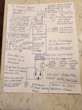
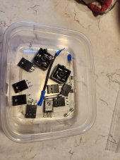
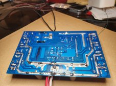
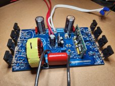
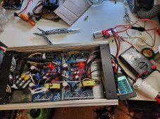
Important things to know, factory boards have an exact measurement between the FETs and work better with individual heat sinks (example picture in the very first post) new FETs you install yourself can be have the leads bent in a Z shape to assist in easy assembly into a standard inverter case heat sink. All boards will require 6 copper insulated wires about two feet long soldered to the circuitboard, two for DC power input + and -, two AC output wires hot and neutral, and two smaller wires for CPU power can be AC or DC power 12-18 volts 16 factory recommended.

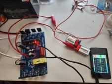
Recommended low voltage testing 12-18 volts DC when building the up the power boards until you see a stable output signal from the board, solder copper wires directly to components like diodes, diode bridges and double check every connection.
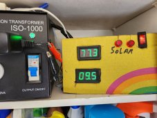
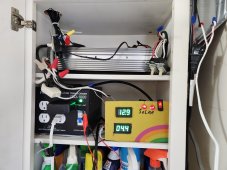
Nothing should make a noise during normal operation except the fan and start up/ shut down noise of the ISO transformers.
Any hum,hiss or pop noise from the inverter case is bad news likely a bad connection but could be the result of bias damage to components, bias damage will build up a static charge to the point of shorting out the FETs or diode bridge ends with components damage and a short of the DC 180 volt buss. Depending on how the ground is connected to the power board bias damage occurs from instantaneously to a max of three days later when the sun was full on PV array and the diode bridge failed, ISO transformers prevent this mess and actually make the system preform stable across all levels of operation.

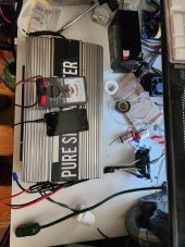
Starting at the heat sink/case apply a thin coat of thermal paste next the FET isolation pads and install the power board. Normally I temporarily put a layer of cardboard underneath the board to insure spacing, use proper hard ware and screws to snuggly attach FETs to case or heatsink. I reused the parts from the old inverter removed from the case, watch YouTube videos on inverter FET replacement to become proficient. Not hard once you see it done.

Taking a break, Lots more on this subject ?, Just review the thread and ask questions if you need help.
 
Last edited:
Back
Top