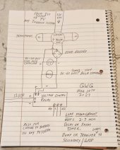
diy solar

diy solar

New no battery pure sine wave solar power system with smart switchers.

Several different ways to use and configure the project system.

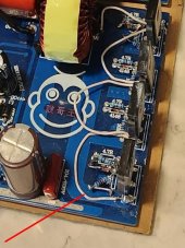
Not recommended by this projects 200 max voltage rule, but have heard back from the UK several 220Volt AC 50 Hz systems have been built using the same power board and 40N65 MOSFETs.

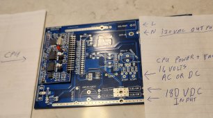
These power boards have been on the market for at least 10 years for inverter repair and upgrades to pure sine power.

The project tamed the strong bias to earth ground found in other power systems, set up PV solar for direct drive input to the power boards, corrected the pure sine power for real neutral/earth ground and rounding the sine wave for really clean AC power.?

I don't regret anything in building the project power system, you benefit from having a proven concept solution road map to follow. The more I do the easier it all gets. Proficient in FET upgrades,testing and CPU replacement on the power boards, New zero grid usage on a sunny day makes me smile every time I go out the back door and see it.?

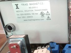
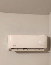
Recent improvements making a real difference in the fun factor, easier to build, use green power and save, completely solved heat issue in running the mini split 24/7 off the secondary ISO transformer, on the right path after years of hit and miss testing ?

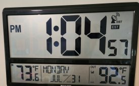
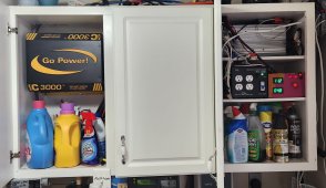
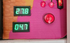
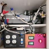
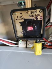
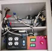
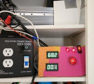
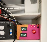
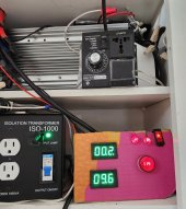
Normal operation 75.0 on top display would be the full 15Amp PV solar have witnessed 14.68 Amps without a problem, bottom display is total grid usage tiny reverse leak on a rated 15Amp diode bridge 0.01 backwards no forward flow so Zero secondary usage.❤️
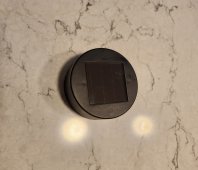
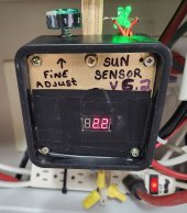
Note green indicator of the ISO transformer is off, full sun detection has opened the relay circuit to the primary coil fuse, Zero grid/secondary usage.

More soon
 

Attachments

  • 20230725_114658~2.jpg
    20230725_114658~2.jpg
    255.5 KB · Views: 1
Last edited:
Beware of free solar panels offer or the government will pay for your solar panels scam. Look at the 25 year payoff amount the gentleman in the center will be 107 years of age at payoff time, this stuff doesn't cost that much in the first place what I am offering is 15Amps of solar PV at a DIY cost of $4,000.

Most quoted prices/payment plan now days start at 25,000 to 69,000 do the math, average home electric bill is 150-$300 monthly, monthly payments were $385 for the installed power system.

Don't fall for the scams standard solar panels go for $100 each the real cost of the inverter is around 300-500, charge controller 300-500, and batteries can cost thousands but the whole point of this thread is you can ditch the whole batteries thing and still come out way ahead, put the payment plan money or battery replacement cost directly in your pocket. Also natural power blending of the secondary ISO works in any amount of sunlight to keep the money in your pocket.

Through getting burned myself financially I have come up with a better way to do no battery solar power, not many things make me happy but this one does right now under less than perfect solar sky conditions the A/C is blowing cold.

What is going on right now 10:30 AM, sky conditions picture,90 degrees Fahrenheit outside 74 degrees inside, system is running smooth.

My system either drops the big loads to off or via a delayed switcher unit transfers big loads to grid when solar input is not great enough to run the appliances. It works and 24/7 seamless power can be increased to bridge or smooth out the operation to your custom needs.

I am liking the stand alone no grid usage in sunny conditions of the project system ?

Best wishes to all

Noticed the views on the mini-split 120VAC version, three quarter ton, inverter drive compressor, impressive cooling and moisture removal from the air pulling 850 watts in normal operation/ winter heat pump defrost pulling a 1000 watts!
 

Attachments

  • 20230727_094801~2.jpg
    20230727_094801~2.jpg
    342.5 KB · Views: 4
  • 20230727_102829~2.jpg
    20230727_102829~2.jpg
    296.3 KB · Views: 3
  • 20230727_102655~2.jpg
    20230727_102655~2.jpg
    223.8 KB · Views: 4
  • 20230727_102750~2.jpg
    20230727_102750~2.jpg
    66.6 KB · Views: 9
Last edited:
I push this equipment hard every day to find the limits and maximize the solar payback.

If the house lights start flickering with a 70-71 degrees Fahrenheit set point rising the setpoint to 75-77 degrees and the unit will reduce it's power requirements, works good late on a hot afternoon, also late afternoon I turn on a grid powered mini split to efficiently continue cooling into the evening hours.

Unit running smooth on a mostly sunny day,

IR blaster and app can fully automate this action for next summer.

Swapping out to the big combo unit tonight, comparative testing the two slightly different builds, Have discovered the DY002-2 CPU will automatically resume in most cases if you simply reduce the load, Just automatically recovers about 10 seconds on the restart sequence, lead power board on the big combo has the DY002-2 CPU.

More later
 
Last edited:
Sun just starting to rise and the big combo inverter is on and ready for testing, supposed to be a mostly sunny day.

Pushed the slim inverter yesterday to the limits and it survived, since I have a ready made backup today it's the big inverters turn. I have the lead power board with the DY002-2 CPU and 40N65 FETs Pushing the main output ISO transformer.

Black box with knob is ventilator fan speed controller, all is temporary till I complete this phase of testing, planning a couple of holes in the cabinet and rerouting the wires so the door closes normally.

More later on actual test results.

Lead board has an issue,likely a bad connection faltering under 1/3 load conditions, good news secondary board just sustained 13 amps for 20 minutes straight, just going to swap outputs and continue testing, lead board will be a DY002 CPU and four 40N65 MOSFETs.

Best news so far is the problem is limited to board #1 inside the inverter case ?
Swap complete on the power board outputs, just need more sun, Monday is forecast to be blue sky?

Best wishes
 

Attachments

  • 20230729_064446~2.jpg
    20230729_064446~2.jpg
    172.1 KB · Views: 3
Last edited:
The project has split I am going to make a note for others about the what's good about each approach.

I am going to follow the no grid usage in full sun configuration for awhile to see if I can improve on smoothness of the operation, this configuration is providing the most efficient use of grid/secondary and still allows for 500-550 max watts after hours power. Uses normal factory ISO transformer 117volts and sun sensor turns off secondary ISO power when full sun is detected with a twelve volt relay 15Amps.?

The previous version shown In the diagrams is the seamless and MPPT full sun ISO boosted configuration, provides a more robust operating platform,This configuration consumes a small amount of grid/secondary power 24/7 830 watts seamless support available/ normally one third amp with full sun, I may in a short time of testing return to this configuration❤️

More soon
 
Last edited:
Wow, Lots of surprising data coming from the current line of testing. In a nut shell:

The system works OK for PV only operation but system voltage is around 98VAC when pushing full loads and flagging (Flicker or dimming of LED bulbs) starts sooner with the big loads under 100% PV.

ISO boosted mode with a factory 117 volt transformer instantly pushing the system voltage up to 110 VAC with the same loads and much more robust operating conditions, for the one third amp secondary/grid usage you get a much more stable platform for your electronics.

I will make the stand alone mode switchable for grid down situations but main focus from here on out is boosted seamless power and boosted MPPT full sun effect.?❤️

Glad it was properly tested both ways but I am getting at least one third more usable power from the boosted configuration in full sun ?

Think I located the bad solder connection on the #1 power board, your power production system is only as good as it's weakest link!

If done correctly this system really works, many companies have gone out of business recently for installation of equipment that burns out and stops working, external disconnectors and external micro inverters are the leading cause for failure in the new systems.
Keeping electronics cool and dry is important especially when the process itself generates heat, roof top temperatures have been high this year.

Nice diversion but must get back to cooling/powering the home, speaking of diversions amazing what is not reported in news now days. Bernie made off with your money Jr walked away scott free, you know who almost scammed his way into the ultimate get out of jail free card while you were watching aliens and lava flow?

A huge Canadian fire left to burn all summer is not climate change, back in the 50s it was hotter than it is now, any serious science experts should tell you we don't have enough data to know for sure, I see a real effort in the US to go green but other countries are just building more coal fired power plants and laughing at us, in the new GDP data the US will be dead last in the coming year.

More soon
 
Last edited:
Fixed the #1 power board bad connection on the 120VAC output, Installed a bypass switch on the secondary ISO so 24/7 550watts of seamless can be locked in permanently unless it is switched to PV only operation. Normal boosted 117 VDC secondary ISO 24/7 is the ticket for best operation.?

Tomorrow is supposed to be a blue sky day, if the unit is still running at 5PM it will likely be left in place for the foreseeable future to run the home, major stress testing in store for the big combo inverter.

Wish me luck only stress testing because I have a plug and play ready backup and more glass fuses if needed.

More later
 
It is done large inverter has passed all testing and is every bit as strong as the slim inverter, to prove the point you will only see the large inverter for the project in the future used as primary power production unit, the slim unit will be a plug and play backup.

Listen up page 22 documents are correct (I got it right the first time), this thing makes one amazing platform for your electronics, the secondary ISO input transformer is critical I recommend 15-16 amp medical grade (Same ratings for the output transformer), It does not require any modifications except the diode bridge for the output to the power boards run this 24/7 for seamless 550watts prefered output, provides efficient voltage boost for the entire system and MPPT boost for your solar panels, Both way testing has proven the input boosted is the correct way to run the power board, only change I recommend is omitting the negative side blocking PV diode for extra current to the power board and it allows for more MPPT full sun boost. I am really on to something here air conditioner and overhead lights say I got it right ✅

Amazing performance, Amazing ?

Use mono crystal panels, medical grade ISOs, 40N65 MOSFETs makes for a rock solid reliable power production system, best I have ever seen ❤️

The system has been bullet proof for months now, no matter what I do it automatically recovers or a simple reboot of the power board CPU, the only way to kill it is a full system surge or for the output transformer to get out of sync due to a loose connection and fully surge the power board. Aways soft start the system, configure CPU power and secondary ISO together to cause the soft restart when power is restored!
Avoid changing the main configuration when running, avoid messing with cords and plugs when in operation.

Testing:
Maximum current measured though the power board FETs:
In PV solar only mode 14.68 Amps (15amp max) at 98VAC system volts.
Boosted ISO 16Amps through the powerboard FETs 110VAC system volts 1.8 amps from secondary.

More soon

6PM not the blue sky day that was that was promised but still 76.8 degrees Fahrenheit at the end of the solar day.
 

Attachments

  • 20230731_130457~2.jpg
    20230731_130457~2.jpg
    245.9 KB · Views: 1
Last edited:
Starting tomorrow I will put the final touches on the wiring and reroute so the cabinet door closes normally.

Super happy with recent test results ?
I have the system I want and plenty of backup parts/units to keep it going well into the future.

Panels are rated for 80% power in 20 years, 15 new mono crystal panels, 24 poly crystal ranging 3 to 9 years of age.

Not that hard to DIY one for yourself, Here to guide you if needed.
With standard 100watt solar panels three nine panel series 180VDC arrays 5amps each for 15Amps total, other size panels work fine target is 180VDC.

More later
 
Last edited:
Again nice work,and thanks for your contribution.
A few Q

1. Can AC out of Sine board be parallel by wire to double KVA output?

2. Which is rate of KVA for OUT iso transformer,is 830 right?

3. 16 VAC cannot be taken of on Out side sine board I guess.

4. Is this thin white wire is only on right Fet just for testing,left Fet is without wire ?

5. How sine board know to pull more DCV from PV than from AC grid,on supply side sine board?

Can you inlite me.
 

Attachments

  • pb.jpg
    pb.jpg
    80.1 KB · Views: 3
Again nice work,and thanks for your contribution.
A few Q

1. Can AC out of Sine board be parallel by wire to double KVA output?

2. Which is rate of KVA for OUT iso transformer,is 830 right?

3. 16 VAC cannot be taken of on Out side sine board I guess.

4. Is this thin white wire is only on right Fet just for testing,left Fet is without wire ?

5. How sine board know to pull more DCV from PV than from AC grid,on supply side sine board?

Can you inlite me.
A#1 Have attempted to sync multiple power boards to the same CPU for double the KVA, as with all known 8FET configurations it gets unstable especially under full loads, In testing full loading of the secondary board causes opposing FETs to short.
Not recommended by this project but more real watts of power can be channeled through the power boards by increasing the input voltage (380 VDC in getting 240VAC output)

A#2 Secondary ISO transformer with 115 VDC out provides 550watts of seamless after hours power, 23 extra turns nets 830watts, 63 extra turns 1,200 watts on a 15Amp ISO. (Hi voltage warning going past 23 turns). In full sun conditions per powerboard 2,000 watts continuous output and 2,500 watts surge how long depending on the heat sink efficiency.

A#3 CPU 12-16 volts AC/DC needs to be from a isolated source like a single solar panel,or battery or if you are unsure run it through a doorbell transformer as AC.(If you try to run it for example from a grid powered power brick 12VDC or 12VDC from a negative ground battery based solar PV system the power board will instantly explode in the center of the power board)

A#4 The thin white copper wire is mimicking the power board traces for increasing the amp transfer across to the pure sine choke, the two resistors and diode on the four corners of the power board were added on top of small wires because of reused parts with short delicate leads. Two 8FET boards have been built and one synced combo all were unstable, the 4 FETs 40N65 MOSFETs version is very stable.

A#5 Natural voltage controlled DC power blender circuit, trick of nature where the higher voltage wins in a direct connection blend situation (simple 180VDC solar VS 115VDC from grid/secondary) Solar wins in the most efficient way possible and the money stays in your pocket.

Will add more here a bit later

Have gone to multiple power boards/combo units to run more stuff.
Current project system has two 2,000 watt boards for 4,000 watt capable unit, wish others were actively helping me to solve this issue.

Another perfect solar day ?
 
Last edited:
Thanks,that clear lot for my "big" knowlege.

1- Yes it will be too easy to use 2-3 board in parallel,like at AC we can on same phase (live) or even different phase by transformator.
Perhaps solution for some use like 3*110 on primar,sec also 110 ,but more price?

2- I do not know your standards,but i guess that you use 9000 BTU .
My 12000 BTU ,no inverter ,I think no soft start just classic one,on 230AC here use 4.5 Amp and wo data about start Amp.
That is reason I look in this 5000w hoping to deal with 12000BTU,as I see same to yours:
1s-l1600.jpg

Ali 5000.jpg

Do you think this is useful?
The 40N65 is 40 Amp by data for inductive loads,does some more power FET can give bigger load ?
I respect your statement that 4 FETs are better than 8,but I believe that 5000w above have 16 at min.

3- So is 16 ACV is manly to adjust 50 Hz,supply also?
 
Thanks,that clear lot for my "big" knowlege.

1- Yes it will be too easy to use 2-3 board in parallel,like at AC we can on same phase (live) or even different phase by transformator.
Perhaps solution for some use like 3*110 on primar,sec also 110 ,but more price?

2- I do not know your standards,but i guess that you use 9000 BTU .
My 12000 BTU ,no inverter ,I think no soft start just classic one,on 230AC here use 4.5 Amp and wo data about start Amp.
That is reason I look in this 5000w hoping to deal with 12000BTU,as I see same to yours:
View attachment 160706

View attachment 160707

Do you think this is useful?
The 40N65 is 40 Amp by data for inductive loads,does some more power FET can give bigger load ?
I respect your statement that 4 FETs are better than 8,but I believe that 5000w above have 16 at min.

3- So is 16 ACV is manly to adjust 50 Hz,supply also?
Although I have never owned the boards you are showing they are known to me as the 4,000 and 5,000 watt versions of the 1,000/2,000/3,000 wattage boards that have been used in the project system.

I assume if you follow the same basic project system rules as the 3,000 watt board you can get more amps out of a single board, I invited you to try the larger boards and let us know how it works for you, beware of anything with an earth ground the larger boards will need the same ISO transformer protection and corrections as the smaller version.

50Hz/60Hz power is a jumper selection on the power board CPU. CPU power is 12 to 16 volts AC or DC on the smaller boards. More than 4 FETs requires the full 16 volts AC or DC to operate.

Mini-split heat pump is a three quarter ton about 9,000 to 10,000 BTUs of cooling.

Boards cannot be paralleled unless they are 100% synced. Have only seen it work one time and it failed once the secondary board approached full load.

Invite any improvements. If you have success with the larger power boards or air conditioner I may purchase one myself.

Invite anyone to expand on what I have working so far, the setup I have working is great but lags a bit in the hot late afternoon hours.

Power board inverter has no transformer, input voltage determines output.
380 VDC in is 240VAC output
360 VDC in is 220VAC output
180VDC in is 122VAC output project system ?
Everything is under 200 volts✅

Best wishes
 
Last edited:
Wiring corrections have been made all cabinet doors close now.

6VDC small solar rooftop panel for the Sun Sensor voltage controlled relay is still working but the surface of the solar cell is blistering and cracking in the full sun.
Replacement is a 2.5 volt solar cell from a brand new yard light, DC voltage controlled relay will need recalibration.

System exceeding expectations on a overcast sky day ?
Non stop solar Air conditioning 9AM to 4:30 PM, 76.6 degrees Fahrenheit indoors at end of solar day.

More soon
 

Attachments

  • 20230802_171653~2.jpg
    20230802_171653~2.jpg
    173.4 KB · Views: 3
  • 20230802_171902~2.jpg
    20230802_171902~2.jpg
    130.3 KB · Views: 3
  • 20230802_171745~2.jpg
    20230802_171745~2.jpg
    337.7 KB · Views: 3
Last edited:
Hi,I am very,very limited of electronic.
Strange that 16 V can be AC or DC,but just for supply I got it.
No one seller say it,but that is just seller.
Best
 
Hi,I am very,very limited of electronic.
Strange that 16 V can be AC or DC,but just for supply I got it.
No one seller say it,but that is just seller.
Best
The power board circuit board has 4 diodes arranged as a diode bridge so no matter if the input is AC or DC it ends up DC powering the power board computer and cooling fan. On the 1,000-3,000 watt boards 16 volts is recommended, on the 4 FETs 40N65 MOSFETs boards 12VDC or 12VAC works great. Must be Isolated from earth ground or serious damage to the power board will result.

Be careful to discharge 180VDC capacitors before working on the power board units after use or testing pass/fail.

Close up views of your power boards reveal markings for 320-420VDC input and 220VAC output (same thing with the smaller power boards) No guarantee that 180VDC input will give 120VAC output first try around, I am curious about what you are trying to do but warning 320 VDC is exceeding dangerous and requires lots of solar panels to get 220 VAC power.

Best wishes,be careful ?
 

Attachments

  • 20230803_184929~2.jpg
    20230803_184929~2.jpg
    397.3 KB · Views: 4
Last edited:
Have swapped out 6VDC solar sensor cell on the roof with new 2.5 VDC solar cell, working but more calibration will be nessassary in full sun conditions.

Actually prefer the 6 volts cell but it was in the process of failure.

First picture blistering and cracking 6 volt cell.

Second Picture new 2.5 VDC solar cell from a new yard light.

Official solar sensor version 6.2 Instead of shorting out the solar cell input with the potentiometer it will sample the voltage from the load, early testing says this is a better solution less load on the tiny solar panel.

Early picture the epoxy glue is still hardening but it is live and running full solar on a day you wouldn't think it could work.

Based on a cheap $11 voltage controlled relay from Walmart, add and remove loads from your system or energy capture to batteries on any system, Nessary to have one on the project system.?

Just keeps getting better, recent improvements and recommendations make it easier to build and run.

More soon, best wishes

Program for relay 2.5 volts max sun power.

2.2 volts relay is energized full sun
2.0 volts relay is off after hours mode

It works very well right now but I need to see rolling clouds, sun up/down events to give it the royal stamp of approval.

August 5th blue sky day, Project system has delivered nicely on everything even at 100 degrees Fahrenheit including the green lawn mower recharge,Picture
 

Attachments

  • 20230804_114302~2.jpg
    20230804_114302~2.jpg
    189.6 KB · Views: 1
  • 20230802_171902~2.jpg
    20230802_171902~2.jpg
    130.3 KB · Views: 1
  • 20230804_154055~2.jpg
    20230804_154055~2.jpg
    179 KB · Views: 1
  • 20230805_154503.jpg
    20230805_154503.jpg
    82.2 KB · Views: 1
  • 20230806_123739~2.jpg
    20230806_123739~2.jpg
    224.2 KB · Views: 1
Last edited:
Put final touches on the wiring for the Sun Sensor but need to add a second 2.5 VDC solar cell on the roof to add range to the digital relay, unit did not go into night mode till 7:30 PM last evening, normal should be around 5:30 PM.

Need more voltage steps and a load resistance to adjust the sensor, the six volt solar cell was much better suited for this job just needed to be a better quality part.

Update to previous photos.

Best wishes
 
Package of 100 high quality wire ties with metal cleats are due to arrive today, New system has no batteries but older system has four flooded deep cycle batteries, just finished with maintenance on them, used one and three quarter gallons of distilled water, two of the four batteries had the top of the plates exposure above the electrolyte. (Not good!)

All four serviced and passed electrical testing (good for another three or four months) obviously this summer has been ruff on the batteries.

Planning to revamp the old and new systems and eliminate unused components and reroute/optimize the wiring, new route will eliminate half the wiring to the top of the cabinets.

Both inverters working great, the larger inverter has operated the air conditioner recently in over cast conditions that was an amazing surprise, switching to the slim inverter because I think it runs slightly better under high load conditions and the wiring is simpler on the thin one.

Project Systems will be shut down tonight for a couple days during the upgrades and changes.

Several high and low voltage capacitors will be put into this case pictured.

Shutting it all down, rebuilding it for simplicity and robust operations.

Best wishes

More soon
 

Attachments

  • 20230807_185722~2.jpg
    20230807_185722~2.jpg
    127.8 KB · Views: 1
Last edited:
Except for the solar PV inputs this has become a gut job, Total rework of the entire system old and new.

Expect a couple more days to sort things out, have a master plan for the main (solar-off-grid switch) and removal of the large DC 12volt cables across the top of the cabinets.

Big surprise at sun up this morning although the battery array was disconnected and all the inverters were switched off the newest 100 amp charge controller activated the 12VDC buss that also activated three more MPPT charge controllers, reconnected the batteries and letting it top off the battery array that was serviced yesterday down by one third and charging.

Work on the old system will continue after dark tonight, today will rework everything to do with the new system and ISO outputs.

More soon

About 3 or four hours away from from restart on both systems, two hours after dark for safety on the older system.
High and low voltage capacitors have all been placed in a nice looking box, with removing the non functional DC bus wiring it will have a cleaner look.

Still a few things to figure out, Both systems restored at 9:30 PM✅️ still another hour or two of clean up and wire ties to work on tomorrow, cleaned up 5 or so years of layered crap and removed about one half laundry basket full of unused parts and wire?
 
Last edited:
12:00 Noon everything running smoothly 72.5 degrees Fahrenheit inside.

Preceding zero on the bottom display indicates less than one amp of secondary/grid usage.

I am done with changing any of the power components for a long time.

Going to explore using the voltage controlled relay to watch the system AC voltage instead of just sky full sun detection/conditions.

Have previously considered running the system this way but did not have the $11 programable relay to work with.

In a nut shell turn on big loads if system voltage is 111VAC or greater and off if below 99VAC.

As with everything due to limitations of the relays 99volt maximum a small step down transformer will be needed, diode bridge, small capacitor, indicator bulb as a load also time control may be needed for after hours to prevent false starts.

Only reason for this testing/exploreration is the sun sensor as it sits right now is lagging a bit till I add another rooftop small solar panel 2.5 volt DC to increase the range, a couple days back the sensor stayed on in overcast conditions and ran the mini-split all day long just fine.

Need to know if system voltage control can squeeze out more good solar days for air conditioning.

Here I go again about to make another big step forward ?

More later
 

Attachments

  • 20230809_114008~2.jpg
    20230809_114008~2.jpg
    378.4 KB · Views: 1
Last edited:
6AM Excited at the new power system voltage monitor I just built. 120VAC input translates to 9VDC output.

Double pole switch will allow for either system voltage monitoring or full sun detection with the DC voltage controlled relay.

Light bulb is the load and if you look closely you can see the glowing filament, tiny capacitor is a DC filter and the circuit has an ultra fast response time.

Transformer is 120VAC input to 9VAC output, diode bridge,filter capacitor and load.

Have high hopes this approach will gain extra days of green power on lightly over cast days by letting the system say what it can and cannot handle at any given time.?

The voltage controlled relay also has timers, going to program it for instant off at below 99VAC system voltage and 2 minutes delay before going back on at 111VAC or above so the relay does not act like a blinker.

Have already seen this work for a full day by accident and with a time control that is already in place and working I can prevent false starts after hours on changing system loads, this is going to be great.?

Simple low cost parts that will squeeze every drop of green power directly to running your stuff with the project power system.

Had to add an additional filter capacitor, making forward progress. Sun pops out and it actually works, see drawing for details, see pictures running heavy loads.

Diagram is a mega cheat sheet, this $11 relay could be adapted to any PV power system for load management and Battery charging.

Delay timers in the switcher units have everything working perfectly, also have the switch working for solar sensor or system voltage control. (System voltage controlled is best so far!) only using voltage control mode on the programmable relay ?

More soon ❤️
 

Attachments

  • 20230810_064959~2.jpg
    20230810_064959~2.jpg
    237.5 KB · Views: 1
  • 20230810_141041~2.jpg
    20230810_141041~2.jpg
    145.4 KB · Views: 1
  • 20230810_140627~2.jpg
    20230810_140627~2.jpg
    262.2 KB · Views: 1
  • 20230810_140314.jpg
    20230810_140314.jpg
    202.3 KB · Views: 1
Last edited:
No one is looking but I just solved the the problem of clouds/overcast sky in the best way possible for the project system,only dumps or transfers the large loads if the power board is getting in trouble.

7 minutes delay before any of the large loads can return to the power board and that is only if the power board has fully recovered to 115 VAC?

It is brilliant and the details are in the previous post, simply put the power board is protected by a $11 computer controlled relay and timers.

Here it is a detailed drawing of this simple and cheap solution to clouds and overcast sky on the project system it may be applicable to other PV systems.

Possibly one of the most important diagrams I have ever made as this can in real time protect any solid state PV inverter from a voltage crash situation with preset limits. Save you big time it can.

Final picture ( I will make it pretty later), Fully functional system voltage load controller, fully automatic, Toggle switch up system voltage controlled, Toggle switch down full sun detection mode, automatic timer sets 9AM to 5:30PM daily load management.
 

Attachments

  • 20230810_154731~2.jpg
    20230810_154731~2.jpg
    186.6 KB · Views: 2
  • 20230810_141041~2.jpg
    20230810_141041~2.jpg
    145.4 KB · Views: 2
  • 20230810_185050.jpg
    20230810_185050.jpg
    112 KB · Views: 2
Last edited:
New configuration is working great, taking advantage of after noon sun.

The project has become simpler to build:

With monitoring the system voltage and controlling loads no need for an additional wire and solar cell on the rooftop.✅

No additional added windings on the secondary ISO transformer for normal operation.✅

Recommended 4 FETs 40N65 configuration is less complicated and easier to install in a inverter case.✅

Omitting negative side PV blocking diode makes the system work better and reduces costs and complexity of the build.✅

Using the $11 voltage controlled relay(s) for load management and energy capture makes it cheap and easy to fully automate the system.✅

No batteries, No charge controller,Low maintenance, Low/No heat designs, Hi efficiency operation, Glass fuse and CPU protection.✅

Durable low cost solar PV DIY approach.✅

Only parts not shown in the photo is the rooftop solar panels, a second output ISO transformer in the floor behind the clothes dryer, vent fan and voltage controlled relay.❤️

Second Picture name plate view of main output 120 VAC ISO transformer that is located behind cloths dryer also the doorbell transformer 16VAC in the view used for isolated power to the CPU on the power board.

More soon
 

Attachments

  • 20230811_154600~2.jpg
    20230811_154600~2.jpg
    242.1 KB · Views: 2
  • IMG_20220824_114832535~2.jpg
    IMG_20220824_114832535~2.jpg
    220.5 KB · Views: 2
Last edited:
Rounding out day 2 of system voltage controlled load management, multiple $11 voltage controlled relays could fine tune the experience also think a 15 minute timer on the mini-split switcher would be better than the 7 minute timer that is currently in use.

Bottom line it really works even with just one of the relay boards, If the sky conditions don't recover from overcast conditions the the relay will not reset to the (ON) 115 system volt mode, Takes care of itself no matter what.

Secondary ISO runs 500-550 watts nonstop 24/7 operation.

Seriously spent today working on the home theater sound system because I have not had an issue since turning on the system voltage controlled relay.

Win Win
1691868723508.png
 
Last edited:

diy solar

diy solar
Back
Top