diy solar

diy solar

On-Grid Air Conditioning start Occasionally trip Inverter into a reset.

Phoenix PV

New Member
Joined
Jun 4, 2023
Messages
15
Location
Phoenix, Az
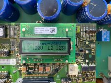
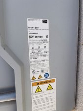
9.02 Kw on grid system with SMA SB8000 inverter - I have recently experienced an Inverter reset issue when my Air Conditioning unit starts (See figure). I have a SENSE monitoring on the PV and load side and can see a power demand spike coincident with the inverter reset. Estimated draw of the spike is 4000 watts at 240 V - appx 15 amps (well within the 40 amp breaker).
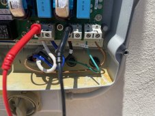
I suspect the voltage may be drooping at the inverter (200 amp panel, AC breaker at the top, PV breaker at the bottom).
I have installed new start capacitors and surge protectors on the AC systems.
AC Start - Inverter reset Peak 9000 watts.GIF
Yellow PV Watts generated (0 - 10Kw). Red is AC load. NOTE: reset one time and not the other with similar peaks.
1) Has anyone experienced this issue?
2) More importantly, has anyone solved this issue?

Surge protectors are looking for spikes, whereas this is a droop.

3) Are there AC "Hold Up Devices" (Power quality) that could minimize the droop.

I appreciate all interactions (even sympathy!)

Best regards,

Mike
 
The Sense may not be fast enough to capture the initial inrush current which is very high but only lasts for milliSec. The AC rating plate should have a value for Locked Rotor Amps (LRA), this is how much current it takes to start the compressor.

Many of us have installed Soft Starters, with good results. Micro-Air Easy Start and HyperEngineering are 2 Brands that seem to be high quality. A soft starter can cut inrush by 70%.
I have installed "Soft Start" kits on each AC. It has certainly cut down the spike (initially 14000 watts). I also agree the Sense may not capture the full spike but certainly identifies the AC start inrush current as the trigger. I will look at these 2 brands. Thank you!
 
Strictly on-grid, correct?
Soft starters (not cheap) are usually for running an A/C on a generator or inverter.

I expect inrush to be 5x operating current, and well over the breaker size used for A/C circuit.
The grid and your wiring ought to be able to supply even a stalled A/C motor until the thermal breaker finally trips.
If Sunny Boy disconnects, it is seeing too much voltage drop, maybe shares a high resistance connection.
Is all wiring to SB and to A/C separate except for 200A panel and grid connection? Maybe the bad connection is there. You could check for heat, voltage drop across connections, difference in voltage between phases.

If it was a newer SB like -41, the UL-1741-SA parameters would ride through longer. But SB 8000US just has UL-1741

I've had my SB upset by non-PFC VFD, but that was off-grid.
 
Hedges,

Thank you for your information-filled reply!

Agree with the inrush assessment and the voltage droop as the likely cause.
The AC and PV systems are connected to the same 200 Amp service through individual breakers.
Wires are independently routed (insignificant chance for conducted interference).
I did change the PV breaker (thinking like you thought a high resistance connect) to no avail.

My next steps:
1) Will try to capture the Hi/Low voltage with a min/peak meter.
2) Will review and torque all connections in the PV circuit from the panel to the inverter.
3) I will also install a panel surge protector (Likely not help this but great for the spectacular lightning filled monsoons that are coming).
4) Any thoughts on whether changing the AC breakers would help (Will also retorque the connections)?

Thanks again for this insight and response.

Will keep the group posted.
 
Unless it caused so much drop that A/C was slow to start or didn't start, I don't think branch breakers contribute to the problem.

I'm guessing that something in the common path (main breaker, wires, meter, utility connection) has excessive voltage drop. Or, voltage from grid is too low (check that.)

Maybe you can find a bad connection in the common path. With high current (load or GT PV production) DMM can show voltage between terminals, or terminal to wire. After a long time operating, it can also show up with non-contact thermometer or IR camera.

But sure, torquing and tug-testing everything might help. I think I've had wires not under the screw. Wire strands settle - I rotate back and forth, tighten more, repeat. The torque given by instructions doesn't itself compress them enough.
 
What ton capacity is the AC system? How frequently are you starting? Frequent starts will not allow the pressure to bleed down and will increase the load on the compressor.

For my moms house I installed a 14KW Generac NG standby that runs her 3-ton AC unit. Generac recommended a 20KW generator, as the 14KW really grunts when starting the AC compressor.
 
Delmar,
I am currently seeing about 15 minutes of rest between end of a cooling cycle and beginning of the next cycle. Temperatures are about 100 - 105 this time of year. How much time would you expect?

Hedges,
Well here are the results . . .
1) Will try to capture the Hi/Low voltage with a min/peak meter.
- Found worst case minimum voltage to be 117 Volts for the "Air Conditioner start spike"
- Spikes to 119 did not cause the inverter to go off line.
- This is clearly causing the inverter to go off line.
2) Will review and torque all connections in the PV circuit from the panel to the inverter.
- Re-torqued all connections in the AC and PV circuitry - No change.
3) I will also install a panel surge protector (Likely not help this but great for the spectacular lightning filled monsoons that are coming).
- Installed surge protector on the 200 amp panel - No change
4) Any thoughts on whether changing the AC breakers would help (Will also retorque the connections)?
- Did not change the breakers (4 ton and 5 ton AC units - This is an On-Grid system).

A couple of other thoughts for discussion:
5) Currently the PV beaker is on the bottom of the 200 Amp panel and the AC units at the top of the panel.
- Do you think moving the PV breaker to the top would help (Closer to the incoming source)?
6) Perhaps a dumb question but I and reaching for straws at this point . . .
- Has anyone installed a "Hold Up" capacitor in their system (in line with Line 1 and/or 2 similar to a run capacitor.
- Not sure if this would even work. Any suggestions on size from the electrical engineers and electricians (if not a laughable suggestion)?

I really do appreciate the participation in this mystery!

Best,

Mike
 
I wouldn't expect capacitors to hold up AC, only DC.
Capacitors could be part of a surge suppression system.

117V for a 120V nominal line? That's not enough to knock an inverter offline. Something else might, much lower voltage or frequency/phase shift.
Any chance the meter can't record brief dropouts? We bought a meter that was supposed to, but I thought it just had diode-R-C circuit. Some meters are faster. I have been using a scope to look at waveforms, but triggering on dropout would be more difficult. Maybe if scope has track/trend function.

What are voltage settings of SB? Can they be widened?


For SB 5000US,

AC operating voltage range at 208 V nominal value 183 V … 229 V
AC operating voltage range at 240 V nominal value 211 V … 264 V
AC operating voltage range at 277 V nominal value 244 V … 305 V
AC operating frequency range 59.3 Hz … 60.5 Hz

For SB 8000US,

AC operating voltage range at 240 V nominal value 211 V … 264 V
AC operating voltage range at 277 V nominal value 244 V … 305 V
AC operating frequency range 59.3 Hz … 60.5 Hz

2 x 117V = 234V, 2 x 119V = 238V, very close to 244V.

Any chance your inverter is configured (or has auto-configured) for 277V?
 
I will review the 277 VAC aspect tomorrow!! Great thought!

One other weird aspect. I have Sunpower panels with a Positive ground. I don't believe that to be an issue since the DC is rectified to AC before is passes on to the grid.

I also agree on catching the spike. Need a trigger scope that is not a part of my toolkit :( .

Again, I appreciate the assistance.

Mike
 
Transformer isolated inverter, so no interaction between DC grounding and AC voltage.
I've got many inverters of that series, which I now use negative PV ground for AstroPower and Sharp, positive ground for SunPower.
For one year I used a transformerless SB 10000TL-US with all three brands paralleled.

I'm hopeful it is 277V setting, within a couple percent of the issue.
The circuit I had transformerless on, didn't include neutral. The SB 8000US I have there now I used jumpers to specify 240V.
Others, I included neutral and set jumpers so it autoselects.

I think I could use that feature with SB on 208V of 3-phase, then if I manual transfer switch to 240V split-phase it will auto configure.
Another member with SB -41 accidentally wired for 120V, and it worked! 277V is not supported, and when N is tied to L1, and undocumented feature is 120V operation. (those models have 120V secure power feature.)
I've picked one up and may use it for a 120V only SI/SB system.
 
Hedges,

Reviewed the wiring and jumpers (Used for voltage correction). All looks correct per the manual.

I did notice that the measured input voltages are 121.5 and 121.3 but the display reads 118 and 121.
Wondering if the voltage sense circuit on the inverter board has gone/is going bad.
Interestingly the "240" voltage readout reads 242 . . . Correct for the measured input.

The saga continues . . .

Will keep posted.
 
Transformer isolated inverter, so no interaction between DC grounding and AC voltage.
I've got many inverters of that series, which I now use negative PV ground for AstroPower and Sharp, positive ground for SunPower.
For one year I used a transformerless SB 10000TL-US with all three brands paralleled.

I'm hopeful it is 277V setting, within a couple percent of the issue.
The circuit I had transformerless on, didn't include neutral. The SB 8000US I have there now I used jumpers to specify 240V.
Others, I included neutral and set jumpers so it autoselects.

I think I could use that feature with SB on 208V of 3-phase, then if I manual transfer switch to 240V split-phase it will auto configure.
Another member with SB -41 accidentally wired for 120V, and it worked! 277V is not supported, and when N is tied to L1, and undocumented feature is 120V operation. (those models have 120V secure power feature.)
I've picked one up and may use it for a 120V only SI/SB system.
I was very hopeful on the 277 also. :(
Thanks for the good info. I have read that the transformer-less could be used on the Sunpower panels, perhaps with some performance loss.(?)

Any thoughts on moving the breaker closer to the panel input?

Not sure there is a lot of damage going on with the inverter (2 minutes to reset - 2 - 5 times a day), although I do hate cycling the electronics unnecessarily. May work for many years to come. As you are also aware, these SB positive ground inverters are becoming hard to find.

Thanks again.
 
Last edited:
Let's check the 277V a third time.

Use DMM between L1, N, L2, G terminals of inverter and note the voltages.
Take a photo of jumpers.

I was soooo sure it was as good explanation.

Other very likely explanation is voltage glitches too low (or has edges that look like bad frequency or phase), but your instrument couldn't catch it. What exact instrument? Got anything better?

I don't like cycling either, neither electronics nor relay would like that.

SunPower some years ago discovered their PV panels at the time were rapidly degraded by PID when negative grounded (as SMA transformer type GT PV inverters did at the time.) They got these new models from SMA, which can be configured either positive or negative.

Check data sheet for your panels, see if they are "PID Free". If not, this isn't "reduced performance", it is rapid serious degradation of the panel.

An interim fix was a circuit that biased the string negative at night, to partially reverse the ion flow.

A bit of added inductance or resistance in the A/C circuit might reduce the peak current (too much and it won't start.)
This is very helpful. I will tackle this on Monday and Tuesday and get back to you.

I am sure the peak low voltage is not captured. I do have a Newport TruRMS Supermeter that can capture the min. Will need to hook up and see if I can catch it. The auto shutoff will need to be disabled :)

I will take a picture of the connections and the lumpers. A bit hard to see the "Labels" but believe they are correct. Will send a picture though.

I have an electronic version of the panel spec sheets and see if "PID Free".

I do have an inverter that can be set Positively and Negatively grounded. Move a jumper and the fuse position. I have tried post positions with no change in symptoms.

On the A-r Conditioner side I did install a "Soft Start" kit which I imagine may affect the resistance and inductance. I'll see what documentation is available.

Thanks again for your help!!

Mike
 
Last edited:
Positive vs. negative ground PV array with transformer type inverter would have no impact on how grid monitoring works, won't affect this disconnect.

The grounding will apply bias to PV cells, which is where PID comes in (apparently ions driven into cells, poisoning them.) Also, plating vs. etching, similar concept to PID, if there's any electrolyte between cells/traces and frames. Bridges and radiators use anodes, either something like zinc or an electrode with voltage applied, to prevent corrosion.

Soft start should reduce the voltage dropout. It may also make harmonics which confuse the inverter. My Sunny Boys (10000TL-US and 5000US) were both upset by VFD when off-grid and waking up. Try disconnecting your soft starter, see if your on-grid system still trips offline. The soft starter will repeatedly bang sharp edges; it is a variable light dimmer, I think. It may also be a VFD, not sure.

A scope capturing voltage and current would be interesting.

Even if labels are hard to see, it is pins and jumpers I'm looking for. I can compare them to SMA manual.
Ditto for power connections. Want to see if neutral is present, where it goes, what voltage is on it. Simply measuring N-G would show zero volts but not prove it wasn't floating, so when you measure L1-N and L2-N, that should show stable voltage.

After I installed VFD and 3-phase pool pump, I read of harmonics causing damage to motors, so I installed a "reactor" in between. that should heavily attenuate common-mode higher frequencies, reducing currents through bearings. It has been running for years (15?) now. I see articles on VFD, motors with dielectric bearing mounts or slip rings to ground shaft, etc.

To solve my VFD off-grid problem (grid is stiff enough no problem on-grid), I plan to install PFC front end module, 240VAC to 360VDC. Or else wire it direct to grid, not operate pool pump off-grid.
 
The saga continues . . .
Measured:
L1 - N - 121.44 Vac (Operational)
L2 - N - 121.47 Vac (Operational)

Inverter display:
L1 = 120
L2 = 123
240 Grid identified
DC = 350, (353 measured)

L1 - N min capture (when goes off line) - Working to capture the low voltage as I write.
Will update when available.

Here is a picture of the power jumpers and wiring:
Right 4 jumped. (Ens1 to Ens2) and (200V to 100V)
Labels: #5 = 240 Vac, #6 = 0 Vac, #7 = 277 Vac

A picture of the Positive Grounding of the Sunpower panels.
Fuse in Left position. Left 2 polarity pins jumped.

Also a picture of the nameplate (Does not accommodate 208 Vac).
 

Attachments

  • IMG_7995.jpg
    IMG_7995.jpg
    613.4 KB · Views: 2
  • IMG_7996.jpg
    IMG_7996.jpg
    467.6 KB · Views: 2
  • IMG_7999.jpg
    IMG_7999.jpg
    150.6 KB · Views: 2
  • IMG_8001.jpg
    IMG_8001.jpg
    490 KB · Views: 2
  • IMG_8002.jpg
    IMG_8002.jpg
    144 KB · Views: 2
  • IMG_8003.jpg
    IMG_8003.jpg
    534.4 KB · Views: 2
Display suggests jumpers say to auto-select. Wires agree with 240V.

Since configured 277V isn't the problem, my next guess is the soft start. I think that repeatedly turns on part way through phase, maybe upsets SB.

Powered from inverter/battery, soft start should reduce load.

Is your system strictly on-grid? If so, why the soft start? I suggest deinstalling or bypassing it, see if Sunny Boy is OK then.

Maybe a "reactor" (choke) would reduce high frequency noise enough.
. . . . And now for the rest of the story . . . . About a week ago, one of my AC's died (15 years old). Sprung a leak in the condenser coils . . . Guess what, all good since then . . . New one on it's way. Suspecting a struggling old compressor and slow lack of coolant may have been the cause. Of course the saga continues with the new one. Variable speed so start up should be less amperage draw. I will keep you posted.

And yes, 100% on grid . . . But the choke idea I will store away!!

And again, thank you for your interest and insight!
 
If the inverter cannot start and run the air conditioner on battery power, with grid disconnected, there is no reason to have the air conditioner running through inverter pass-through relay. It just puts unnecessary stress on inverter's pass-through relay and causes lower AC voltage at compressor making startup surge last longer in time.

A high air conditioner startup surge current through the inverter pass-through relay and internal inverter wiring can result in a voltage drop from grid AC input voltage to inverter's AC output. The inverter response time to follow a dip in grid voltage is relatively slow so inverter may pick up much of the air conditioner startup surge current.

Phoenix, Az summer temps are brutal causing very high compressor head pressure. Hard on compressor, hard on condenser coils. You want a unit that has large condenser size for its btu rating to get the most heat exchange possible to lower pressures on compressor output.

Also make sure you have a 5 minute off timer to ensure a power glitch doesn't try to restart compressor with a high refrigerant head pressure.
 
Back
Top