diy solar

diy solar

Orion Jr.2 BMS thread

There are some gigavac relays which use only 8mA at 48V. You could drive one of these with a mosfet amp circuit from the BMS discharge enable output.

Do you remember which ones or know how to find them? I was eyeing the MX23 which is 42ma and I thought that was quite low. 8 is crazy low.

The only problem with the Orion Jr is it can only handle 175ma of relay current - including pickup current. I wouldn't stick more than 150 on there. I have two relays as a result so I'm at 200ma right now :cautious:
 
Yeah, I saw that... didn't see a way to find the coil current w/out clicking into each of them. The MX23 has separate coils, too (pickup vs. holding) and that's 42ma. I'll poke around I guess.
I'd also love a contactor that's definitely not polarized (it's not clear to me which ones are/aren't).
 
I'd also love a contactor that's definitely not polarized (it's not clear to me which ones are/aren't).
You mean the coil? Some of the dual coil units use a thermal coil, so they aren't polarized.

As far as driving the contactor, a Mosfet (shown in the orion manual) can be used to switch higher current contactors.
 
Sure, if that's an acceptable risk mediation for you, it works.

The only real issue is a major component failure that results in a passive drain even if the gear is powered off. Not a common occurrence with fully digital equipment. Some inverters have their own internal relay which disconnects the power circuitry. I haven't seen it happen with an MPPT controller, but pwm units have rarely failed as a short circuit between PV and battery.

I would suggest wiring it such that if the BMS locks up, that the system defaults to hibernate/off. If I recall the BMS outputs will go floating when a fault occurs, and will be grounded when enabled.

You do need to evaluate your standby usage. You need enough extra capacity that the bank won't get drawn down to dead before someone can intervene in the event of a power down.
My equipment uses between .2 - .3 amps in RPO mode.

Yes if the BMS fails the equipment will go to standby mode. I will have to check the manual but I think after a certain amount of hours in standby it goes to hibernate.

Thanks for all the advice. I'm leaning towards the RPO route for now and maybe put in a relay/contactor later after I more acquainted with this new battery technology.
 
Do you remember which ones or know how to find them? I was eyeing the MX23 which is 42ma and I thought that was quite low. 8 is crazy low.

The only problem with the Orion Jr is it can only handle 175ma of relay current - including pickup current. I wouldn't stick more than 150 on there. I have two relays as a result so I'm at 200ma right now :cautious:
So does that mean the Jr.2 can drive the MX23 without a relay since it only needs 42ma to latch or am I confused on how this works?
 
You mean the coil? Some of the dual coil units use a thermal coil, so they aren't polarized.

As far as driving the contactor, a Mosfet (shown in the orion manual) can be used to switch higher current contactors.

I mean the contact surface. Many are polarized -- current has to flow across the contacts in a single direction or you'll severely decrease the life of the contacts due to arcing (much like polarized circuit breakers; they're designed to extinguish arcs but that's only effective in a particular direction)
 
So does that mean the Jr.2 can drive the MX23 without a relay since it only needs 42ma to latch or am I confused on how this works?

The MX23 needs 970ma to latch and 42ma to hold. So no, it can't drive this directly.
 
I mean the contact surface. Many are polarized -- current has to flow across the contacts in a single direction or you'll severely decrease the life of the contacts due to arcing (much like polarized circuit breakers; they're designed to extinguish arcs but that's only effective in a particular direction)

I see those gigavac contactors being used on EVs and off grid systems with both charge and discharge, so I assume they must not be polarized.
 
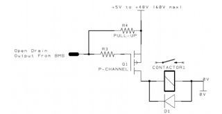
Here is a typical mosfet driver circuit for higher current contactors using the orion or other open drain control source. I used similar circuits to control contactors and a pack heater in my orion pack.

1611201494335.png
 
Last edited:
I tried to locate a SSR that could accept 42-58v input and control the same but I didn't have any luck ...
 
I see those gigavac contactors being used on EVs and off grid systems with both charge and discharge, so I assume they must not be polarized.

The GX11 that I currently have is polarized. It'll work, yes ... and since they don't frequently open it's probably not a big deal, but ...
 
Even if they have higher break cycles in one direction, how often will they be opening at a significant current level? Its probably a lifespan reduction, not likely to be an issue on most off grid applications. Some of these systems might open the relay a few times a year.
 
Rats. I just read the manual for the Victron Battery Protect 48 and it doesn't look like it can be configured to be normally open. So it isn't going to work to connect the RPO wires of my inverter.

Shouldn't a simple relay like this work: 48v relay

I'm in a time crunch to get a relay so need to order from Amazon tonight.

Thanks.

Yes but be careful. You have to get the polarities of everything correct (I had to find the diagram on the amazon listing). I burned out one of the relays by assuming it wasn't polarity sensitive.

Edit: that's why I switched to the relay I have listed in my profile in the About section.
 
Yes but be careful. You have to get the polarities of everything correct (I had to find the diagram on the amazon listing). I burned out one of the relays by assuming it wasn't polarity sensitive.

Edit: that's why I switched to the relay I have listed in my profile in the About section.
How do I find your profile. When I click on your Avatar it's not available. Thanks.
 
Yes but be careful. You have to get the polarities of everything correct (I had to find the diagram on the amazon listing). I burned out one of the relays by assuming it wasn't polarity sensitive.

Edit: that's why I switched to the relay I have listed in my profile in the About section.
So if I want to use the multipurpose no. 1 to power the relay I connect multipurpose no. 1 to the positive input of the relay and use the ground wire (white wire no. 6 in manual) to relay ground. Then connect RPO wires to normally open terminals of relay. Does this sound right? My relay experience is limited to installing HID lights on motorcycles and cars/trucks.

Using the multipurpose out allows me to set less conservative low and high cell values as a failsafe?
 
Put them as close to the inverter as you can.
Are the ferrites sized to fit a single battery cable? or a pair?
Pretty hard to do differential mode filtering of a 500A cable; takes a lot of magnetic material to not get saturated.
Very little choke needed for common-mode with both positive and negative cables going through, because their currents cancel. Only the difference causes any magnetic effect.
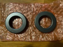
My inverter came prewired with 4/0 cable from the + and - bars to the inverter + and - connections. Came with two round magnets to go over each 4/0 cable I believe. I'm guessing they didn't install them because they would bounce around during shipping.

3.jpg
 
Back
Top