diy solar

diy solar

Packs in parallel, different discharge currents

Fpoet

New Member
Joined
Nov 9, 2020
Messages
74
So I have done a final top balance on my eight 280 Ah Eve cells and assembled them in two 4S packs with two Overkill BMSes. Since it will be a few days before I install them in the van, I decided not to leave them at full charge, so I put the packs in parallel and I am slowly discharging them to about 70%. Now, I was expecting both packs to split the load equally, but one pack discharges at about 7 A and the other one, at 4.5 A.

Normal?
 
I'm putting together pretty much the same setup but haven't paralleled them or installed them yet either and you're scaring me!

Are you checking amps on the bms app or with an amp meter? Are all the wires on both packs equal length and gauge? It could maybe be high resistance in a connection also. I'm not one of the experts on here though but just a couple things that come to mind.
 
a few things to consider when you want precise measurements:

1)have you tested your test equipment to make sure the readings are accurate and consistent? If your meter readings vary by 20%, well...
2)take multiple current measurements at different points so that you can understand where issues may be; e.g., read current at each battery, then at a common point, these readings "should" add up.
3)test each battery seperately with the same load to see how they respond (perform all your test point measurements)
4)test internal resistance of each battery pack (if you do not have a battery resistance meter, test 3 will give you a hint)
5)as techguy pointed out, cable length and connection resistance matter; measure the voltage drop across each section of cable during the test(not across +/-...but literaly measure the voltage drop from your battery connection pt to your busbar on positive cable, then do same for negative cables.)
6)make sure your two BMS's are configured the same
 
Thank you both for the replies. The current readings I am getting from the Klein meter concord with those from the BMSes, and they do add up. I switched the parallel leads to the inverter and I am getting the same current readings from the same batteries, so it appears one of them has higher resistance. I have braided busbars on all the cells so I will have to check the connections. It may be that I have a very, very slight difference in length between the BMS (triple) leads to the negative terminals.
 
How are you discharging them and how are they wired? Any pics of wiring?
No pics, I just disconnected the setup. I was discharging the packs through my Samlex PST inverter. Both batteries were hooked up in parallel (positive to positive and negative to negative) using 2/0 gauge wires of the exact same length and the positive from one pack was connected to the positive terminal of the inverter, and the negative from the other pack to the inverter. The leads from the batteries to the inverter are also of the exact same length.
 
I would be looking for a connection with some resistance. Does not take much to unbalance a very low resistance circuit.
 
My preference is to not have any wiring between the batteries. Each of my 4s batteries goes straight to the fuse (positive) and the shunt (negative).

As suggested above, check all your connections. Put a finger on them (or an infrared temperature sensor) to see if there is one that is warmer than all the others.

If you don't have two ammeters then you're not getting the amp reading from each battery at the same time. The amp draw can vary from second to second, but probably not by much. When I've done a relatively high amp draw against my two batteries, the amps have been within 1 amp of each other. But I'm NOT using two ammeters, so there is plenty of room for variation due to the time required to switch from one battery cable to the other.
 
If there is a difference of Amps from moment to moment, comparing Ahrs over longer time period might be more acurate.
 
My preference is to not have any wiring between the batteries. Each of my 4s batteries goes straight to the fuse (positive) and the shunt (negative).

As suggested above, check all your connections. Put a finger on them (or an infrared temperature sensor) to see if there is one that is warmer than all the others.

If you don't have two ammeters then you're not getting the amp reading from each battery at the same time. The amp draw can vary from second to second, but probably not by much. When I've done a relatively high amp draw against my two batteries, the amps have been within 1 amp of each other. But I'm NOT using two ammeters, so there is plenty of room for variation due to the time required to switch from one battery cable to the other.

I built the packs in two separate boxes, each with its own terminals, so that they are easily removable.

The current readings I am getting with the ammeter are rather stable, no worries there.

Impossible to find a hotter connection by touch. I wish I had an infrared temperature sensor.

What I did so far is submit each battery to the same load through the inverter and each one is providing 11.75A plus or minus 0.1A, which is consistent with the load connected.
 
The current readings I am getting with the ammeter are rather stable, no worries there
What has changed since your original post? Was it instrument error or possibly slight differences in IR at high SOCs of the two packs? That would explain the cell deltas I get when I try to take my pack above 3.5 volts per cell.
 
What has changed since your original post? Was it instrument error or possibly slight differences in IR at high SOCs of the two packs? That would explain the cell deltas I get when I try to take my pack above 3.5 volts per cell.

Actually, nothing has changed. When I connect the packs in parallel and hook them up to the inverter, the two BMSes report different discharge currents, i.e. 7A and 4.5A, and I get the same readings when I measure the currents on the two parallel jumpers (solidly crimped 2/0 wires). The total Amps is consistent with the load connected.

But when I connect each pack separately to the inverter, as was suggested by Diysolar123 above, the discharge current from each pack is the same.
 
Do you have a diagram or picture of your normal battery/inverter layout?

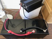
There is no "normal" layout yet, but here is a picture of the temporary setup to discharge the packs some until I can install them in the van. Please note that I just removed the fuse on the positive wire going to the inverter (to see if that makes a difference - no difference).
 

Attachments

  • fullsizeoutput_3e8.jpeg
    fullsizeoutput_3e8.jpeg
    69.5 KB · Views: 14
There is no "normal" layout yet, but here is a picture of the temporary setup to discharge the packs some until I can install them in the van. Please note that I just removed the fuse on the positive wire going to the inverter (to see if that makes a difference - no difference).
In the normal layout, the positive will go to a T-class fuse and the negative to a shunt.
 
There is no "normal" layout yet, but here is a picture of the temporary setup to discharge the packs some until I can install them in the van. Please note that I just removed the fuse on the positive wire going to the inverter (to see if that makes a difference - no difference).

Your wiring is perfectly balanced.
Single fuse to inverter wouldn't cause imbalance.
(Separate fuses could. I had 60' of 6 awg wire from grid through two parallel inverters to load. Current draw was imbalanced 3:1; turned out problem was difference in resistance between two Square D QO270 breakers. Changing to Schneider DIN mount 63A breakers fixed it.)

My guess is poor contact of busbars to cells. Some people have had hot busbars and uneven cell voltage readings according to BMS.
Apply a heavy load to one battery (about 100A) and see what voltage BMS reports for each cell. Use a DMM to measure voltage from cell terminal to busbar, and from busbar to next cell terminal. (NOT from one busbar to the next; no reason to include 3.2V of cell when trying to read 0.01V drop across contact.)

What treatment did you give the cell terminals before assembling pack? (removal of native aluminum oxide, corrosion inhibitor, torqueing of bolts, etc.)
 
While you have the system under load, and you have the current difference, measure all of the cell voltages with the same meter. Try to measure on the actual cell terminal, not the buss bar. If the 4 cells add up to more than the total reading, then you know you have a bad connection. Also measure from cell terminal to cell terminal across a buss bar to check for voltage drop. At 100 amps, you will see a few millivolts on a good connection, but what you are really looking for is one that is different than the rest. If one buss bar is dropping twice the voltage of the others, the you know that is likely a bad connection. At full charge, above the knee, it is not that bad to see a few amps difference. If you increase the load to 100 amps, and the difference is still less than 10 amps, it is not that bad. As the cells come down below the knee, they should balance out. With the very flat discharge curve and low internal resistance on LFP cells, it only takes a tiny state of charge difference to cause a current balance error. After just a few minutes though, the string that is pulling more current will drop it's state of charge a little faster and therefore the internal voltage will slowly balance out and the current difference will fade down. This is a self balancing effect. Both during charge and discharge, the cell pulling more current will catch the ones at less current until they reach a balance point. If one pack has more actual capacity, it may just run the whole time at a little more current to reach full and empty at the same time as the weaker cell. If it is less than 10% different, don't stress over it. Just know you can't pull 2x the current of one pack, maybe just 80% more with a second pack, to allow for the imbalance. If you have 2 batteries rated at supplying 100 amps, you may only be able to pull 180 amps before the stronger battery is at it's 100 amp limit, while the weaker one is at 80 amps.
 
Here is how the Pro's do it:

 
Your wiring is perfectly balanced.
Single fuse to inverter wouldn't cause imbalance.
(Separate fuses could. I had 60' of 6 awg wire from grid through two parallel inverters to load. Current draw was imbalanced 3:1; turned out problem was difference in resistance between two Square D QO270 breakers. Changing to Schneider DIN mount 63A breakers fixed it.)

My guess is poor contact of busbars to cells. Some people have had hot busbars and uneven cell voltage readings according to BMS.
Apply a heavy load to one battery (about 100A) and see what voltage BMS reports for each cell. Use a DMM to measure voltage from cell terminal to busbar, and from busbar to next cell terminal. (NOT from one busbar to the next; no reason to include 3.2V of cell when trying to read 0.01V drop across contact.)

What treatment did you give the cell terminals before assembling pack? (removal of native aluminum oxide, corrosion inhibitor, torqueing of bolts, etc.)

Terminal treatment: terminal face sanded with 600 grit paper, cleaned with acetone; studs JBwelded into terminals; braided bussbars with smaller holes drilled and contact face filed, sanded and cleaned with acetone. No corrosion inhibitor, no washer on top or underneath the bussbars, serrated nuts tightened at 30 in/lb.

In a capacity test, I pulled the same capacity with this setup as my initial test with the Basen provided bussbars (at about 0.2C - 40 A).
 
Back
Top