diy solar

diy solar

Use solder paste on terminals-busbar to improve conductivity?

Or a stud with large nut between battery and busbar, so more torque could be applied to busbar connection without over-torquing the weaker thread in the battery.
For normal mechanical situation, yes
Here is the copper contact to the aluminium the most important factor.
The stud is the least conductive part in the whole setup.
(A stud of aluminium/copper might work, not locally for sale, not in China.
Iron, 304, carbon steel, enough threaded rods and headless bolts.
Aluminium and copper? None.)

Yes, thin layer is more easy flatened then thicker.
Good for me they are flat and don't need it. :)

One most important part of "the best way" is availablity.
(Vs usage, time and costs)
Getting oxi-guard is really expensive if I want to use it this month.
Or even next Month.
It's cheaper to get silver conductive paste.. $2.50 for 0.7 ml
Only little bit is needed.
And here next week.

I'll make a new post for building the "optimal powerbank" from LiFePO4 cells :)

Or atleast my efforts to make it,
With pictures.

Almost all parts are in.
Now I need to solder my remaining 0603 thermistors onto wires to measure the temperature of the cells.

That will need the microscope again :)
 
I think when you use anything conductive there is potential for electricity to follow the path if you get sloppy or if over time it gets smeared around.
 
Hedges. I am so respectful of your knowledge. But, what you picture is not what I addressed. You stated a "nut between the batter and bus bar". Never do that. If anyone wants to read more about stuff like washers on battery connections , with pictures, check here,; https://marinehowto.com/battery-melt-down-narrowly-averted/

Agreed, and what the link showed with insufficiently torqued nut and stainless washer in the current carrying path are both bad.

It quoted a standard as saying, "10.8.5 Flat washers, if used, shall only be installed immediately under the split lock washer and nut of the attachment stud." which certainly makes sense for incompatible materials.

Following all the rules/guidelines is generally the way to go. In some message board threads, people have had problems with short studs integrated into the battery terminals that didn't fit the multiple thick bussbars they wanted to use. Several possible ways to address that, including standoffs made of suitable materials (aluminum, lead, tinned copper) depending on what it has to contact. For instance, you've seen lead battery terminals with steel screws that thread into side terminals on batteries. That's just another kind of standoff. But I haven't found any suitable copper or aluminum nuts or stand-offs commercially available. Custom thread-on terminals would have to be machined and plated.

The problems people seem to be having is that the torque a battery terminal can withstand is low compared to what they would like to use for battery cables. Besides compressing the ring terminal, a cable exiting at right angles to the stud has considerable leverage to loosen the thread, which would cause all the same problems as improper connections. I encounter similar problems with right angle vs. straight SMA coax connectors. Proper torque isn't sufficient to keep the right angle ones from loosening. Maybe a short, limber wire from battery to busbar should be used. I used 10" 4/0 cables for all my battery terminals, but those are 8mm thread which allow a decent amount of torque. Those connect busbars or fuses before cables to the inverters.
 
My approach is the do capacity testing at max design current and measure temperatures at all junctions and joints ( if possible ). No significant temp rise over ambient means a good junction, low resistance and low loss. Temp readings occasionally will show up possible corrosion etc.
 
So many experts. making things so complicated. great read. but i give up to all these folks that say they know so much.
 
Some weeks ago I wanted to measure the resistance of some large braided copper bars I found (about 1 m long, 42 mm2 cross sectional area, more or less the same as a 1AWG wire, I think). Using a 4 contact setup (pass 10 A using 2 contacts, measure voltage "inside" with 2 additional contacs) I found the wire to be 0.5 mΩ/m (more or less what it should be). However, the CONTACT RESISTANCE (if I measured the voltage on the bolts rather than on the braid) was about 4-5 times higher (I had not been very careful cleaning, putting the right torque, etc.). So for short connections the contacts may be the biggest issue, indeed!
 
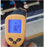
I found a IR temperature gun to be very helpful in testing connections. Push some amps through the battery and test temps at each connection point and connections with higher resistance show up in a hurry.

View attachment 20731

I find our Interns fingers to be the best indicator ... NO NOISE is good ... "umm" is a little warm ... "UUUMMM" is probably getting too warm ... and "HOLY @#$*" and the smell of Bacon we know the BMS is not doing its job ...
 
I find our Interns fingers to be the best indicator ... NO NOISE is good ... "umm" is a little warm ... "UUUMMM" is probably getting too warm ... and "HOLY @#$*" and the smell of Bacon we know the BMS is not doing its job ...
How many of you have held the soldering iron tip close to your nose to test if it is warm and then actually touch your
nose by mistake - ouch ? it’s still hot ! Surely I‘m not the only one ?
 
Follow-up: I had a 2AWG wire to test a crimp connection. The bare wire measures 0.5 mΩ/m (which is exactly the same as what the tables specify). I added a crimp connection on one and (using a Temco hyraulic crimper) and that added only about 0.1 mΩ to the connection (could be more, I am at the limit of detection for my setup). At 200 A (not that you should do 200 A on 2AWG) this would be an added loss of 4 W per crimp. Not terrible, I believe (though probably enough to warm up the area). I have to assume that connections between terminals and bus bars and between bus bars will be worse (maybe significantly so). Has anybody tested this?
 
How many of you have held the soldering iron tip close to your nose to test if it is warm and then actually touch your
nose by mistake - ouch ? it’s still hot ! Surely I‘m not the only one ?
I thought I might be the only one who used this method to see if the iron is hot!
I haven't touched my face with it though.
 
So many experts. making things so complicated. great read. but i give up to all these folks that say they know so much.
I get where you are coming from. I get plenty of flack for recommending a spray-on, connector lubricant and avoiding dissimilar metals for a simple, long lasting solution.

@Hedges, it seems like we have similar backgrounds. I too have done plenty of time working on avionics and manufacturing where material science and Engineering converge. I have some disagreement with some of your conclusions, but your reasoning is usually sound. ?
 
If it doesn't move, but should. Use WD-40. If it moves but should not. Use duck tape.
 
Hedges. I am so respectful of your knowledge. But, what you picture is not what I addressed. You stated a "nut between the batter and bus bar". Never do that. If anyone wants to read more about stuff like washers on battery connections , with pictures, check here,; https://marinehowto.com/battery-melt-down-narrowly-averted/
Thanks for that link. I used a washer improperly and am now fixing it.
You may have saved me a nasty fire or worse. :)
 
Thanks for that link. I used a washer improperly and am now fixing it.
You may have saved me a nasty fire or worse. :)
Be sure to use a torque wrench.
Terminals in a battery are held by the strength of the plastic, which isn't much compared to metal. Too much torque and you break the seal, which could result in leakage or battery degradation. Possibly a greater issue for your lithium than my lead-acid.
 
Be sure to use a torque wrench.
Terminals in a battery are held by the strength of the plastic, which isn't much compared to metal. Too much torque and you break the seal, which could result in leakage or battery degradation. Possibly a greater issue for your lithium than my lead-acid.
Everyone says that BUT.....
What poundage of torque?
And are ALL lifepo battery cell terminal the SAME torque?
That is why I go by feel.
Like the guy falling out of the building said. "So far so good. :) :ROFLMAO: :p
 
Everyone says that BUT.....
What poundage of torque?
And are ALL lifepo battery cell terminal the SAME torque?
That is why I go by feel.
Like the guy falling out of the building said. "So far so good. :) :ROFLMAO: :p
Well if you had simply followed MY advice and used AGM, you could just RTFM!
(Oh, that had been for someone with a stationary application. Yours is mobile. Carry on ...)


"Terminal torque values: M6 use 35 in-lbs, M8 use 70 in-lbs"

I think that also was a sticker on my batteries.
For yours, have to look for documentation, specs from a bigger name brand, or troll through these threads, see if it has been answered.
Seems like there are such small thread sizes in these lithium battery terminals you're more likely to strip them out than rotate the terminal.
Some of the threads discuss using a stud not a screw, bottoming it by hand and backing out slightly, using thread-lock.
Don't want you to have to fix mangled threads either, which someone experienced with a short screw.

Read through this "thread", if you haven't already:

 
Last edited:
"Terminal torque values: M6 use 35 in-lbs, M8 use 70 in-lbs"
Well being an old woman I think I can manage 35 in-lbs. Oh wait, I was a power lifter for 30 years and lifted the back end of small cars for funsies. hmmm. LOL ;)

I will read those articles. Thank for the links. :)
 

diy solar

diy solar
Back
Top