diy solar

diy solar

Planning the (permitted) system upgrade for my house

Do you have time of use billing?
For some of us, 4:00 to 9:00 PM is when rates are highest, so we would delay the charging.
We are also told than is when the grid is most strained. It is not actually time of highest consumption, but PV has tailed off faster than consumption.

Is 3 hour charging cycle sufficiently benign for the batteries? (I suppose if you've only used a fraction of capacity then it is actually a very low rate.)
Would want to use stage-1 rather than stage-2 charging when you've got all night, if it extended battery life.
Would want to reach fully charged just before driving off in the morning, rather than holding at 100% all night. Or better yet stop at an estimated lower level, e.g. 70%? (Most of the time; bringing to 100% occasionally to rebalance.)
We charge to 90%, and the 3 hours is enough for my car, but occasionally my partner and I drive separately. Right now we are just using the portable cord and share between the two cars, but I have two wall connectors sitting in the garage that were installed at the old house, but we are going to do those at the same time as the Sol-Ark install.
 
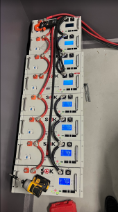
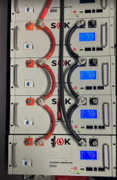
The batteries are all the warranty returns I could scrounge up from the shop... I wanted to get at least some batteries up and going temporarily. I'm going with an outdoor rated rack for them (details coming soon) and there will eventually be 12 total...this was just all we had for returns at this point.

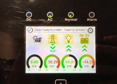
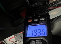
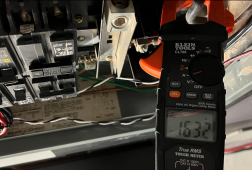
Load tested the system by charging 2x Model 3's with the wall connectors (48 amps each) and everything I could turn on in the house except the A/C. I'll do that load test this summer. None of the connections got even slightly warm so there is a good amount of confidence.

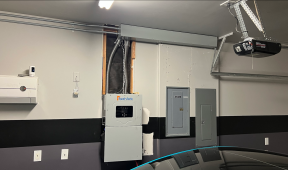
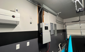
I ended up going with a critical loads panel (the one on the right) because I did not want the power to go out with both cars charging and overload the unit. The non-critical loads come out of the main panel (in the middle).

The sol-ark MPPT is doing horrible in partial shading, but I have not yet updated the firmware since this thing was unboxed almost a year ago.

I put the wireway up top mainly because if it were down below, I wouldn't be able to park in the garage anymore. With 120 degree summers, the A/C'd garage is very important to me. I don't think I've ever observed an install done this way.

1678802496152.png
1678802556958.png
1678802604844.png
1678802635304.png
1678802675041.png

SOC started whack because WGAF, they balanced out perfectly after 2 cycles.
1678803282470.png
 

Attachments

  • 1678802525361.png
    1678802525361.png
    1.9 MB · Views: 13
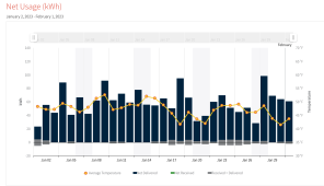
For the thought track of our usage, here is wintertime usage
1678803549450.png

The solar part is coming soon, I'm waiting to get my Tigo TS-4-O's in...I really needed the battery backup on the house ASAP because it cost me about 10 hours the other day when the power went out for a bit and I wasn't home to shut down the backup server (they ran the UPS dead) and things got all out of sync, and cluster'd from loss of power. It was a totally avoidable headache.
 
The sol-ark MPPT is doing horrible in partial shading, but I have not yet updated the firmware since this thing was unboxed almost a year ago.

I suppose that would be due to an array with series/parallel into a single MPPT?
Or, is there some interaction of MPPT voltage limits between multiple MPPT?

If one MPPT input has something like 12s2p array attached, there can be some unavoidable loss if one string is heavily shaded compared to the other.
Also, the MPPT can get stuck on a local maxima and miss the higher peak.
If can you plan your shading wisely (rearrange wiring of panels) so both strings get closer to equal shading, it should help with both of those.

What kind of panels? Are they half-cut wire may be wired something like (18s2p)3s ?
Those create more distinct local maxima, so panel arrangement and wiring may not avoid local maxima, and you have to rely on MPPT algorithm to search the voltage space for highest peak.
If shade moves in from one direction, and/or if it hits entire side of array vs. one panel at a time, panel orientation (and array series/parallel assignment) may help with the situation.

Of course firmware update may partially or fully fix it. Depending on where shade hits series/parallel arrangement of array, rewiring array may still provide improvement.

I'm waiting to get my Tigo TS-4-O's in

Best to optimize array/panels/shading before having Tigo locally optimize voltage/current from individual panels.
 
Nothing like an event to concentrate the mind on a project LOL.
Those returned batteries, any of them actually faulty and needed repair or was it just all customer boo boos. Just curious.
 
What kind of panels?
Aionrise 330w panels. It's a string of 12 sitting on the concrete Will Prowse style. I have considered the obvious things pertaining to shading, but don't want to push the issue further until I update the firmware. Time permitting. Not like I'm loosing much with the amount of cloudy days we've had lately.

Nothing like an event to concentrate the mind on a project LOL.
Those returned batteries, any of them actually faulty and needed repair or was it just all customer boo boos. Just curious.
To be frank, the failures are so few and far between I can't remember exactly without pulling out the RMA forms from my desk. Generally speaking we fix any issues in the field so they never need to come back to us. Thinking back on it now, a couple of them were shop testing units from last year. I know one was a return that had a bad cell that I replaced. Another had a failed temp sensor the customer wasn't comfortable replacing.

Here's a video covering some progress throughout the install. The video turned out boring. It was a lot of work, my house was without power and I wanted to get the job done. Not my finest work, but loads of detail here.

 
Aionrise 330w panels. It's a string of 12 sitting on the concrete Will Prowse style. I have considered the obvious things pertaining to shading, but don't want to push the issue further until I update the firmware. Time permitting. Not like I'm loosing much with the amount of cloudy days we've had lately.


Number of cells: 60 (6 x 10)
Voc 41.3V
3 bypass diodes


Perc cells 0.761V

60 x 0.761 = 45.66 Voc

Seems to just one series string, not half-cut and parallel/series connection.
So no funny behavior with shading.

Only one string?
The worst I would expect is for a shadow covering one row of 6 cells to cause loss of that panel.
If the MPPT is stupid, shading of half a cell could cut power in half. It is supposed to lower voltage until that cell's section is diode-bypassed.

Maybe momentary clouds cause SolArk to switch charge modes? People have described loads applied/released changing battery voltage and charge mode.
Yeah, you're thinking the same thing as me. I thought I'd loose those panels only, but somehow I was loosing about 90% of the string output. The MPPT was parking the voltage at a % of VOC instead of doing a sweep like I've seen on other MFG's MPPTs...So this is why I think a firmware update will fix it, because I recall someone posted on this forum that they got a ton more output from their 15k after a firmware update that changed the MPPT algorithm...I just can't find that post right now.
 
Aionrise 330w panels. It's a string of 12 sitting on the concrete Will Prowse style. I have considered the obvious things pertaining to shading, but don't want to push the issue further until I update the firmware. Time permitting. Not like I'm loosing much with the amount of cloudy days we've had lately.


To be frank, the failures are so few and far between I can't remember exactly without pulling out the RMA forms from my desk. Generally speaking we fix any issues in the field so they never need to come back to us. Thinking back on it now, a couple of them were shop testing units from last year. I know one was a return that had a bad cell that I replaced. Another had a failed temp sensor the customer wasn't comfortable replacing.

Here's a video covering some progress throughout the install. The video turned out boring. It was a lot of work, my house was without power and I wanted to get the job done. Not my finest work, but loads of detail here.

I couldn't tell in the video. But, I hope that you corrected the grounding and bonding in those panels.
They are sub panels and the neutrals should be separated from ground.
 
I couldn't tell in the video. But, I hope that you corrected the grounding and bonding in those panels.
They are sub panels and the neutrals should be separated from ground.
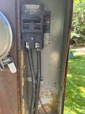
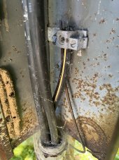
The part of the main panel that is outside is integral with the part inside - the main breaker section outside has no neutral/ground bond, it's done in the main panel inside - so it's not a subpanel and neutral/grounds can be shared on the same busbar.

On the other hand, the critical loads panel is a subpanel, so they are isolated entirely. In fact, the circuits fed by the critical loads panel have their grounding conductor terminated on a common ground bar in the wireway at the ceiling with a #6 grounding conductor from the common ground bar to the chassis of the critical loads panel. The neutrals go to the neutral bar isolated from the chassis.
If your local AHJ accepts that, then i guess you are ok.
But, it wouldn't fly around here. They (outside and inside) are two separate enclosues connected by conduit/raceway. The outside enclosure is the first means of disconnect. Everything after that is supposed to be protected by the N/G bond.
 
If your local AHJ accepts that, then i guess you are ok.
But, it wouldn't fly around here. They (outside and inside) are two separate enclosues connected by conduit/raceway. The outside enclosure is the first means of disconnect. Everything after that is supposed to be protected by the N/G bond.
I don’t completely agree. I asked the electric company and electrician when my cabin meter was changed out. Even though there is a breaker, this is not the first means of disconnect. My panel in the basement is the first disconnect. 274AE679-7896-461A-AE47-A85974EFBFCA.jpeg
C795CA3F-7FA1-4F75-97DD-4161DF264004.jpeg
 
Hopefully, that's the old one.
And it shows part of the N/G bonding.
But, I don't see a ground wire going to the basement panel. Which puts the earth in parallel with the neutral. It should at least be metal conduit with bonding bushings on both ends. But I still wouldn't consider it to meet code.

By simple definition of the words.
That is the "first means of disconnect".
If I recall correctly from the video. The panel that this feeds has main lugs. (No main breaker )
A service is required to have less than 6 throws (breakers or disconnect handles) to de-energize all power. At the first means of disconnect location.

I could swear that I have seen that service before. lol
Around here it's common to see the bottom rusted away like that. Usually at around 15 years old.
They only replaced the meter and was lucky enough to be there to ask. The overall box will be replaced this spring. That ground wire simply goes to the ground and not connected to house in any way and is the correct configuration per the electric company and licensed electrician. They validated I had the correct bond in my main panel which goes to a ground rod at the service entrance. Note that pole/meter is prob 150ft from the service entrance to cabin.
 
Every jurisdiction has their own twist on their interpretation of the code. If it passed in your area, that's all that is required. I can understand their reasoning. It's just not how I would do it.
 
I don’t completely agree. I asked the electric company and electrician when my cabin meter was changed out. Even though there is a breaker, this is not the first means of disconnect. My panel in the basement is the first disconnect. View attachment 139909
View attachment 139910

That's exactly the meter/breaker box I've got, and I don't like that neutral/ground connection, which relies on a teeny #10 screw holding it to busbar.

On the plus side, the 200A main breaker can be swapped with grid power on, because it just plugs on.
On the down side, how can you torque its set screws without breaking the plastic? Nothing to restrain rotation.
 
If your local AHJ accepts that, then i guess you are ok.
But, it wouldn't fly around here. They (outside and inside) are two separate enclosues connected by conduit/raceway. The outside enclosure is the first means of disconnect. Everything after that is supposed to be protected by the N/G bond.
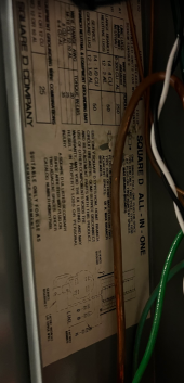
No, they are not connected by conduit/raceway. They are integral to each other in the same sheet metal assembly. This complete assembly is used often in these track homes. "Square-D All In One" I'll get better model no. later, but this has a diagram on the label as well.

1679029143095.png
 

diy solar

diy solar
Back
Top