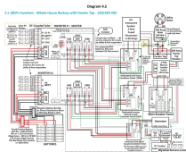
I called the city and they said NEC 2020 and 2021 IBC and IRC.One more thing would be to verify if your are under NEC 2020 or 2023, some of those disconnect rules in 706.15 are relaxed in NEC 2023 and could keep you from having to add disconnects at the inverter if you are under 2023.
You are using an out of date browser. It may not display this or other websites correctly.
You should upgrade or use an alternative browser.
You should upgrade or use an alternative browser.
Please Help With Direction
- Thread starter Fearless
- Start date
Dave911
Solar Enthusiast
I agree with most of what pvgirl said. I would skip the 6 gauge wire to the PV strings. I don't see the point. You are better off running 1 1/4" conduit and use 10 Gauge wire and when you pull in the wires leave in a pull string in case you want to change or add conductors. 10 Gauge is plenty for your projected load. If you price 6 gauge THHN vs 10 gauge you will rethink your wire choices.
So your scheme for moving loads to the solar system is simply to wire them to the 150amp panel rather than the 200 amp panel? Are those two panels adjacent to each other? I thought they where in different parts of your house??
Regarding the mechanical structure for your ground support system. The locations where you use U bolts to secure the cross frames to the tube; You want to get rid of the U bolts. They will slip. Instead make a weldment that attaches (is welded) to the main tube and bolts to your verticals. Also, rectangular tubing is probably a better idea than square. Steel is cheap compared to everything else, overbuild rather than suffer from structure failures. I would have someone run some mechanical analysis of your steel selections. Pillow blocks to support the frame may be overkill. There are a number of ways to allow a pivot without a ball or roller bearing. I would think that a detail of the foundation of your vertical post supports would be required if this is going to be inspected. Rather than putting an actuator on the 2" schedule 80 main tube, I would consider a hand cranked screw with a lever arm, unless you are going to level the assembly automatically if the wind pipes up.
Anyway, nice plans.
Are the net metering rules where you live favorable?
Thanks,
Dave
Dave911
Solar Enthusiast
I agree with most of what pvgirl said. I would skip the 6 gauge wire to the PV strings. I don't see the point. You are better off running 1 1/4" conduit and use 10 Gauge wire and when you pull in the wires leave in a pull string in case you want to change or add conductors. 10 Gauge is plenty for your projected load. If you price 6 gauge THHN vs 10 gauge you will rethink your wire choices.
So your scheme for moving loads to the solar system is simply to wire them to the 150amp panel rather than the 200 amp panel? Are those two panels adjacent to each other? I thought they where in different parts of your house??
Regarding the mechanical structure for your ground support system. The locations where you use U bolts to secure the cross frames to the tube; You want to get rid of the U bolts. They will slip. Instead make a weldment that attaches (is welded) to the main tube and bolts to your verticals. Also, rectangular tubing is probably a better idea than square. Steel is cheap compared to everything else, overbuild rather than suffer from structure failures. I would have someone run some mechanical analysis of your steel selections. Pillow blocks to support the frame may be overkill. There are a number of ways to allow a pivot without a ball or roller bearing. I would think that a detail of the foundation of your vertical post supports would be required if this is going to be inspected. Rather than putting an actuator on the 2" schedule 80 main tube, I would consider a hand cranked screw with a lever arm, unless you are going to level the assembly automatically if the wind pipes up.
Anyway, nice plans.
Are the net metering rules where you live favorable?
Thanks,
Dave
More questions: What exactly is mounted outside? Your batteries and inverter is not outside the walls of your house, right?
Likewise your breaker boxes, the 200 and 150 amp are mounted inside, next to each other and those are inside, correct? I think the PV disconnect has to be outside as well as the meter? That's required in Indiana.
Dave
I shopped around on the 6 AWG and got some really good deals. I'm going to feed both the 150A and the 200A breaker boxes from the inverter. Even though the 200A box has both AC units the 150A box is using more juice. I have a waterfall pump that is using a lot and it runs during daylight hours. It could drawing more amps because of the algae in the pond. I'm using the square galvanized tubing because I got a good deal on those. The pillow block bearings are cheaper than anything I could rig up and it is why I went with round pipe driven by the slew drive. I don't think the u-bolts will slip (there are 10 of them) but if they do, I will solve it. This is going to be an automated east-west track so no manual changing.I agree with most of what pvgirl said. I would skip the 6 gauge wire to the PV strings. I don't see the point. You are better off running 1 1/4" conduit and use 10 Gauge wire and when you pull in the wires leave in a pull string in case you want to change or add conductors. 10 Gauge is plenty for your projected load. If you price 6 gauge THHN vs 10 gauge you will rethink your wire choices.
So your scheme for moving loads to the solar system is simply to wire them to the 150amp panel rather than the 200 amp panel? Are those two panels adjacent to each other? I thought they where in different parts of your house??
Regarding the mechanical structure for your ground support system. The locations where you use U bolts to secure the cross frames to the tube; You want to get rid of the U bolts. They will slip. Instead make a weldment that attaches (is welded) to the main tube and bolts to your verticals. Also, rectangular tubing is probably a better idea than square. Steel is cheap compared to everything else, overbuild rather than suffer from structure failures. I would have someone run some mechanical analysis of your steel selections. Pillow blocks to support the frame may be overkill. There are a number of ways to allow a pivot without a ball or roller bearing. I would think that a detail of the foundation of your vertical post supports would be required if this is going to be inspected. Rather than putting an actuator on the 2" schedule 80 main tube, I would consider a hand cranked screw with a lever arm, unless you are going to level the assembly automatically if the wind pipes up.
Anyway, nice plans.
Are the net metering rules where you live favorable?
Thanks,
Dave
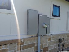
Yes, I plan on mounting the inverter and 2 battery packs outside by the meter. The 150A breaker box is by the meter. The 200A breaker box is in the garage.More questions: What exactly is mounted outside? Your batteries and inverter is not outside the walls of your house, right?
Likewise your breaker boxes, the 200 and 150 amp are mounted inside, next to each other and those are inside, correct? I think the PV disconnect has to be outside as well as the meter? That's required in Indiana.
Dave

Last edited:
Nobodybusiness
Collecting the leftovers of the Great Sky Reactor.
Trust me it’s needed.125kWh/day? I can’t imagine actually needing it!
Nobodybusiness
Collecting the leftovers of the Great Sky Reactor.
Why not just buy another 18 KPV and parallel it?Since I'm close to maxing out the EG4 18Kpv, I'm considering replacing it with two SRNE ASF48100U200-H 10KW inverters.
It's a possibility but moneywise not practical.Why not just buy another 18 KPV and parallel it?
12VoltInstalls
life passes by too quickly to not live in freedom
moneywise not practical
…Trust me it’s needed.
A couple of things to consider, the SRNE is not outdoor rated so it will have to be installed indoors, also you will need to find a battery system that is UL9540 listed with the SRNE(I don't know of any), or a battery UL9540 listed on it's own under the old UL9540:2016 standard(fortress power has some). The EG4 PowerPro will most likely only be UL9540 listed with the 18kpv.Since I'm close to maxing out the EG4 18Kpv, I'm considering replacing it with two SRNE ASF48100U200-H 10KW inverters.
I determined another issue. I installed Emporia monitoring and I see that the peak 15-minute demand for my Tesla charging was 9.4 kws. The number for my ACs was 3.26. The SRNE for now is not parallelable so unless I reduce the charge rate for every Tesla that uses my charge one SRNE will overload.A couple of things to consider, the SRNE is not outdoor rated so it will have to be installed indoors, also you will need to find a battery system that is UL9540 listed with the SRNE(I don't know of any), or a battery UL9540 listed on it's own under the old UL9540:2016 standard(fortress power has some). The EG4 PowerPro will most likely only be UL9540 listed with the 18kpv.
That would work because it would only be an issue when both the bigger AC unit and the charger are running. Then when the AC cycles off the charger could go back to normal.There are smarter EV chargers that can very charge rate depending on load, I believe emporia has one. Also since you are grid connected you could draw excess demand from the grid.
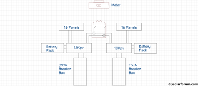
That is one way to do it, although with that design you won't be able to share load/solar/battery between your 2 panels. To clarify this diagram you will need 2 separate breakers right after the meter, for the feed to each 18kpv. Depending on locations most likely you will need breakers or disconnects on the output of the 18kpvs as well.
Similar threads
- Replies
- 45
- Views
- 2K
- Replies
- 3
- Views
- 448
- Replies
- 7
- Views
- 450
- Replies
- 23
- Views
- 867


