diy solar

diy solar

Rapid shutdown switch question

Saw2645

New Member
Joined
Aug 21, 2023
Messages
3
Location
USA
I am installing a 3 pole DC safety switch and a AC safety disconnect next to my utility meter to prepare for the requirements needed to apply for net metering in my area. I have installed the EG4 18KPV, and it has the ability to add a remote rapid shutdown switch(RSD). So I was considering adding it as well, but all the ones I was looking at with their own enclosure are just plastic enclosures.

So here is the question I’m trying to answer: can I install the RSD switch right in the door of either the AC or DC disconnect? Is this allowed? Would there be any issues with this?

Second question, on the 3 pole disconnect for the PV DC input, I see from the spec sheet from the manufacturer that either the negative or positive lines can be broken allowing for up to three strings 30 amp, 600 volts. Am I understanding this correctly? If so, is there a preference as to which one I should disconnect?

Thanks for your time and comments
 
So here is the question I’m trying to answer: can I install the RSD switch right in the door of either the AC or DC disconnect? Is this allowed? Would there be any issues with this?
I don't know. (I don't know of anything that would prevent it, but that just means I don't know.)

Note: To be to code, the switch must be readily accessible by first responders. This means it must be outside. I believe it should also be near the service disconnect.

Second question, on the 3 pole disconnect for the PV DC input, I see from the spec sheet from the manufacturer that either the negative or positive lines can be broken allowing for up to three strings 30 amp, 600 volts. Am I understanding this correctly? If so, is there a preference as to which one I should disconnect?
To be to code, all non-grounded conductors must be disconnected. For almost all modern systems this means both the positive and negative lines must be disconnected.
 
For GT PV, simply opening AC connection with safety switch triggers RSD.
A hybrid of course continues to operate.

What I have today is battery inverter AC coupled to GT PV inverters. When I relocate PV panels to roof, my plan is to use 3rd pole of 3 pole safety switch to interrupt power to keep-alive transmitter (separate box, which I will use with my older inverters that don't have internal keep alive transmitter.

My new system will be different equipment. Once I get battery/hybrid going there, I may use 3rd pole for a relay or use a handle position switch to do that.

This way, a single visible blade disconnect near the meter triggers rapid shutdown as well as isolating inverters from the grid.
In event of power failure, the extra switch or pole would still let battery backup system remain alive.
For security reasons, in case somebody turns off the switch, I'll have a bypass inside so I can restore power without going outside.

What is the DC safety switch for? RSD reduces voltage to single panel Voc < 80v within array and < 30V outside array.
I like to physically disconnect both PV+ and PV- before working on wires. Your switch could do that for one string/array. It could interrupt current for 3 arrays, allowing you to unplug MC4 connectors.

When I had negative ground arrays and used 3-pole safety switch, they disconnected the positive pole.
 
For GT PV, simply opening AC connection with safety switch triggers RSD.
A hybrid of course continues to operate.
I believe the code requires a rapid shutdown initiator and the PV disconnect, but I could be wrong on that.

The 18Kpv has a built in RSD transmitter so if you have RSD receivers, hitting the RSD initiator will do all of the following:
1) shut down the PV lines by stopping the transmitter (PV Rapid shutdown)​
2) Turn off the AC out. (ESS Shutdown)​
3) If you have the new EG4 E-stop batteries, the batteries will shut down. (DC line shutdown)​
 
I need the DC disconnect to meet the utility requirements for net metering agreement. I have proper PV disconnect coming off of my array and one on the 18KPV itself. This safety switch is just to meet the net metering requirement next to the utility connection.

They don’t require the RSD, but with adding it being available, I thought it would be worth it. EG4 shows it as required in their diagram as well.

Thanks for the input.
 
Last edited:
I have 2 6000xp's and am planning to install the RSD switch also out by my main panel & transfer switch, and I have the same question that @Saw2645 has. I have the switch already, and I'm considering just cutting the right size hole for it in the front of the Pro Tran 2 transfer switch case and installing it there without the box. I could use the rubber caskets for the switch and still make it waterproof. I have no idea if that would violate code somehow, but it seems like a better solution than mounting the plastic box on the side of the house...
 
I also have 2 6000xp’s. Currently they are setup as an ESS for backup power (solar panels are planned for spring).

I was planning on putting the RSD outside near my utility meter. I wanted to set it up, so I can add a Tigo for shutting down the panels.

My thought was to put the RSD and eventually Tigo in this enclosure.

Vevor Enclosure

Does this make sense?
I like the idea of putting the RSD button inside an enclosure like that out by the main panel. I don’t see a reason to put the Tigo CCA out there too though - it’s more conveniently located by the inverter. I bring the signal wire from the TAP along with the PV wires from the array to the inverter, connect the signal wires to the CCA there and use the 12 volt dry contacts in the inverter to power the CCA so no other power supply needed. I confirmed that when rapid shutdown is initiated it also cuts the power to those 12 volt connections. I just haven’t mounted the button anywhere yet ?
 
I would think AC disconnect was a utility requirement. DC disconnect might be code, for servicing. But your utility wants DC disconnect.

Are your panels going to be ground mount, and that's the reason RSD isn't required?
I wouldn't use RSD without a reason. More expense, more to go wrong, doubles the number of connections that can fail, has to be same connector as panel or UL listed combo.

Some people want module-level panel monitoring.
 
I like the idea of putting the RSD button inside an enclosure like that out by the main panel. I don’t see a reason to put the Tigo CCA out there too though - it’s more conveniently located by the inverter. I bring the signal wire from the TAP along with the PV wires from the array to the inverter, connect the signal wires to the CCA there and use the 12 volt dry contacts in the inverter to power the CCA so no other power supply needed. I confirmed that when rapid shutdown is initiated it also cuts the power to those 12 volt connections. I just haven’t mounted the button anywhere yet ?

Careful!. I believe the 12V connection will stay on if there is PV power going into the MPPTs.
 
I would think AC disconnect was a utility requirement. DC disconnect might be code, for servicing. But your utility wants DC disconnect.

Are your panels going to be ground mount, and that's the reason RSD isn't required?
I wouldn't use RSD without a reason. More expense, more to go wrong, doubles the number of connections that can fail, has to be same connector as panel or UL listed combo.

Some people want module-level panel monitoring.
For me, I was already using Tigo optimizers on all my panels as they do help with the shading issues I have with my backyard panels. Adding a TAP and CCA only added the wire carrying power and signal between the CCA and the TAP and the power connection to the CCA. My brother is a firefighter, and even though RSD isn't required for me, I do like the idea of providing them that rapid shutdown button by the main panel so that not only is the inverter output stopped but also the PV wires won't kill them if they ended up cutting through them in the process of fighting a fire. The module-level panel monitoring is a bonus ;)
 
Careful!. I believe the 12V connection will stay on if there is PV power going into the MPPTs.
I'm pretty sure I validated that the 12V gets shut down as well even with PV power coming in, but I'll double check tomorrow when the sun is up. ?.

If it turns out that the 12V output stays live, I can just wire the RSD switch to BOTH the RSD switch terminals on the inverter as well as to the AUX terminals on the CCA, which initiates shutdown on the modules even when the CCA is powered.
 
Technically the 18kpv12l has a built in dc disconnect that is controlled by the RSD switch on the side or a remote switch so technically adding an external dc disconnect is not needed, but older requirements may not recognize this as an allowed solution. For example The CA solar guidebook single line diagrams show both external and internal dc disconnect options.
Code wise I believe that you can only run ac in a single conduit and the RSD wire must be in a separate conduit, but it seems ok to have both in the same box as long as the box isn't cut up or modified.
Realistically if the dc disconnect is not right at the panels, you end up with unsafe levels of high volt dc on the pv wires, which is the whole reason why the industry is moving toward the RSD approach where voltage on those pv lines are <80v and shut down with a Tigo or similar device triggered by the RSD switch
 
I like the idea of putting the RSD button inside an enclosure like that out by the main panel.
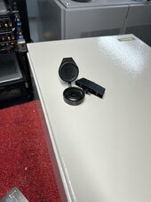
@AZ Solar Junkie - I finally ordered and received that Vevor box I mentioned. It's a no go as an enclosure for the RSD switch as it has to be locked with the key removed to be closed. Not exactly First Responder friendly.

Back to the drawing board.

Nice box that I’m sure I will use when I put my panels up this spring.
 

Attachments

  • IMG_0659.jpeg
    IMG_0659.jpeg
    101.6 KB · Views: 9
@AZ Solar Junkie - I finally ordered and received that Vevor box I mentioned. It's a no go as an enclosure for the RSD switch as it has to be locked with the key removed to be closed. Not exactly First Responder friendly.

Back to the drawing board.

Nice box that I’m sure I will use when I put my panels up this spring.
Sorry to hear that. Thank you very much for letting me know.
 
FYI Many disconnect switches can be fitted with a aux n/o and n/c dry contact switch. These are available from the manufacturer of the disconnect. They mount on the side of the gang assembly and would be perfect as a RSD initiator. You could check if one is available for your switch.
 
FYI Many disconnect switches can be fitted with a aux n/o and n/c dry contact switch. These are available from the manufacturer of the disconnect. They mount on the side of the gang assembly and would be perfect as a RSD initiator. You could check if one is available for your switch.

That's what I got for my Square D switches. (my other plan is 3rd pole if not otherwise used.)
Funny thing that where safety switch is listed in Schneider catalog, it doesn't reference the handle position switch. Only the other way around.

Second photo in this .pdf shows one installed:

 
Back
Top