diy solar

diy solar

Running computers, TVs, and other electronics directly from solar DC (no inverter)

phx

New Member
Joined
Jun 26, 2020
Messages
44
Hi. As far as I understand the electronic circuitry, the absolute majority (if not all) of modern electronic power supplies have a rectifier at the entrance, converting the AC from the grid to DC. Then its built-in inverter turns DC back to high-frequency AC in order to use a tiny ferrite-based transformer instead of bulky 60Hz monsters from the former century.

In theory, such electronics can be fed with DC instead of AC as long as the voltage says in its operating range. However, when I look at the device specification, it never gives DC as an option.
I did some experimenting with several cheap electronic devices like clocks, phone chargers, a power adapter for the router, etc. Even the 10-year-old PC. They all worked perfectly directly from three 40V solar panels (120V DC total) without any inverter. The voltage severely fluctuated depending on the sunshine. But the devices coped with it.
I'm thinking, is it safe to run the "Level 1" EV Charger that way? I believe it has a very similar build.
A wider question - can it be something (besides a big 60Hz transformer) in the electronic devices preventing them from working on DC? It's interesting, why the manufacturers don't certify a DC-based operation of their electronics?
Excellent post and great question. Glad to see your experimentation on this. My panels voltage fluctuates so much, not sure how this would get smoothed out to stay in a safe range, I think is typically 90-140V, at least instantaneously, for many modern electronic circuits. With more solar systems coming online, there will be a growing incentive to make more efficient and compatible systems. The only down side is most systems sold today are grid-tied without battery and offgrid capability so most won’t care about what you are trying to solve.
 
Nowadays, many electronic devices and power adapters are certified by their manufacturers to run from 100-240V AC. That makes sense, allowing them to be plugged into any household grid worldwide: 120V, 208V, or 240V @ 60Hz in the USA, 220V/50Hz in Europe, etc. No voltage converter is needed. In most cases, just a simple outlet/plug adapter or power cord.

If you connect 6 solar panels with Voc=40V, the max possible voltage would be 240V DC, which is still within the certified range of the device. It could drop several dozens of Volts in poor insolation but rarely below 100V DC. Then - the sudden drop to zero when the sun is out. Power blocks usually have electronic stabilizers inside, compensating for the voltage fluctuation on the feeding side.


So, the entire idea looks feasible IF the devices were certified for DC. However, that is the big "IF." It's reasonable to assume that the huge 85" TV would accept DC and wouldn't be fried. But one thing is risking a 10-year-old PC from the attic, and a totally different situation is risking a $2000 brand-new TV. The warranty will instantly vanish with smoke if the TV is fried with DC (uncertified operation).


Bulbs (at least incandescent), kettles, coffee grinders, blenders, vacuums, and other small appliances ( all those with noisy brush-based motors) can run on the DC as well.


So, I see at least two possible implementations of my idea:
1. The cheapest off-grid solar, where you need just panels and wiring. No inverters, controllers, etc. if most of your equipment can run from DC.
2. If all possibilities of growth for the grid-tied system have been exhausted and adding more solar power can be done only off-grid.


E.g. our utility has a 19.999kW limitation of solar for households. If you want to build a 20kW system, it will be treated as "Commercial," must be three phases, have a dedicated AC transformer and comply with tons of other policies for commercial systems. So, the idea to grow beyond 20kW is using a DC directly without bothering the utility company.
 
The trend has been to go with higher voltage with switch mode power supplies. In general, wattages over 180W will use voltage doubling capacitors on the input and these supplies will not work on DC. I run a lot of wall warts on as little as 60V DC at a reduced charging rates. I run a LG direct drive front load washing machines with just panels and a modified MSW inverter. I feed HV DC right into the H bridge which turns almost any DC voltage into AC. No battery is needed and if a cloud passes the washer stops. Once passed the washer can be restarted and it remember where it was. I heat water with DC from the panels with a shunt regulator which keeps the array voltage pretty constant around power point.
 
  • Like
Reactions: phx
The AC rating on thhe power supply is rated in RMS value, the typical switching power supply will have bridge rectifier that convert AC to DC, so if the power supply is made to run between 90 ~ 240VAC, the DC Voltage on the filter caps will be charged to the peak Voltage (V RMS x 1.414 = Vpeak, V RMS x 2.82 = Vp-p), after the bridge rectifier will be 90V RMS x 1.414 = 127Vdc to run the circuit, so if you feed 90VDC to it, the power supply may or may not run and if it does run, it will not be able to run at full power.
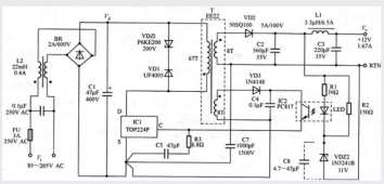
Example of SMPS, C1 Voltage is rated at 400Vdc because if the AC is 265V, then the DC Voltage on C1 can be 265VAC x 1.414 = 375VDC, at 85VAC it will be 85V RMS x 1.414 = 120VDC.
1672516220303.png
 
Thanks, everybody, for sharing your experience and ideas about using the solar DC directly from the panels. I'm looking forward to more stories on the topic.


However, starting this topic, I shared my own experience with my own equipment operating in modes not certified by manufacturers. I would NOT recommend such experimentation for anybody. And if you decide to do similar experiments, please do it on YOUR OWN RISK, not referring to me as a source of recommendations. I would refuse any liability for such actions.
 
>>>filter caps will be charged to the peak Voltage (V RMS x 1.414

That's true only without load. As soon as the IC1/T EE22 - based inverter on the diagram above starts operating, the inductance of L2 would prevent C1 voltage from achieving anything close to 1.41 x AC.


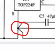
What is this? I have never seen such a component on electric diagrams. It looks like just five wires are connected at one common point. Why is it so special?
1672519989386.png
 
>>>filter caps will be charged to the peak Voltage (V RMS x 1.414

That's true only without load. As soon as the IC1/T EE22 - based inverter on the diagram above starts operating, the inductance of L2 would prevent C1 voltage from achieving anything close to 1.41 x AC.


What is this? I have never seen such a component on electric diagrams. It looks like just five wires are connected at one common point. Why is it so special?
View attachment 127218
L2 is the Common mode filter choke, it is not need for circuit function, it is needed to pass EMI, it will not stop C1 from charging to the Vpeak because Vpeak will always be VRMS x 1.414, you can easily verify by checking out your SMPS, we have engr just for power supply design that i work with.
That drawing indicates star point grounding, proper grounding point is very important when laying out PCB, I use Altium for SCH/PCB layout.
 
Last edited:
It's something I've thought about in the past too, and it certainly works with simple SMPS (Switch Mode Power Supplies).

The problem is the modern / larger units (I would put your card charger in this group) have active power-factor correction (traditional SMPS have poor power-factor) and I'm not sure how this would respond to being fed by DC. It may just work, or it may go fzzt and let out the Magic Smoke.

A lot more research is required before I'd be feeding DC into the AC input of an EV.

 
Last edited:
Those 5 leads coming into one indicates that all board traces must connect to the common pin of the IC to prevent magnetically induced pickup or current induced offsets.

Some PFC chips work perfectly fine with DC. I have server supplies that will operate on DC and the PFC is quite happy to boost the 120V DC input to 340V DC. Other chips may not like it.
 
Back
Top