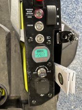
Replaced the round stock battery meter with this one from AiLi/Camway on amazon:
here
You have to widen the hole for the original monitor some with a file/dremel or large step bit to fit the new monitor.
If you decide to attach the new monitor shunt directly to the battery terminal you'll need at least a M8x30mm 1.25 stainless steel bolt to make the connection.
All of the ring connectors are M8 (or 5/16).
Most of the batteries will look for you to use 6awg wire for your actual load current. Shouldn't be an issue if you're using 4 drop-in 12v batteries since you can reuse the original SLA battery wiring in that case. Most of the chargers don't put out high amps, so you can get away with 10awg wire for charging.
I bought some 10-12awg SB50 Anderson plugs from Amazon:
here
If you needed a quick SB50 10awg adapter with ring bolts you can get a pair at a decent price on Amazon:
here
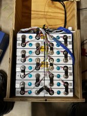
Because of the voltage drift on my batteries I am going to try these voltmeters attached to each battery since they can be manually calibrated. Bought them off Amazon:
here
The nicer looking voltmeters I originally bought had some pretty inconsistent readings even though they looked nicer. I may explore it further, since they are easier to install, but no way to calibrate them. Bought from amazon
here.
Depending on the batteries you get, you may want to charge them up then run a load test to validate the capacity. I had good luck with this one recommended from Will Prowse on his youtube channel that I bought from Amazon
here.
For other cables and adapters of different lengths and gauges with different Anderson plugs I found a good and cheap source to be from BatteryCablesUSA.com such as see
here.
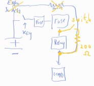
I bought some simple toggle switches to turn off my voltmeters to avoid any trickle drain on the batteries off Amazon
here.
If you need any decent extra lengths of wiring at different gauges off Amazon
here
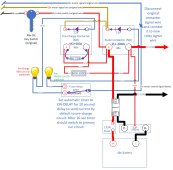
I have been trying to reuse the existing ezgo tri plug with the mower with Dakota Lithium 48v charger. I didn't want to cut off my original charger handle so I bought this pre-made set on Amazon and simply added a 10awg SB50 connector to it. Here is the ezgo charger handle
here.
I'm sure we will all look forward to hearing what results you have with your conversion and which batteries you went with. In retrospect I wish I had just paid more and bought a single 48v pack vs the four 12v batteries and just used some kind of cargo tiedown strap to secure the 48v to the battery tray. At this point it isn't worth investing that much more into the mower vs just getting a newer generation battery mower from one of the manufacturers. The "science experiment" part of this conversion has lost its appeal vs the cost involved and the need to have a functioning mower!
Good luck!