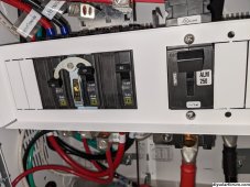
I have attached a pic of the inverter breakers. Does this look right? I will try to get a better pic tomorrowIf you wired it up as shown there, with critical loads panel, and that screenshot is with >100w load on the loads panel then I could only suspect you have the breakers in bypass mode. More pictures of the actual unit or wiring would help.
AC1 backfeeding is used either for exporting or with an upstream wattnode for grid shaving upstream, or with a schneider backup control switch for backfed backup. It's not something I have experience with but it does mean there are possible configs that intentionally don't use a critical loads panel at all. It sounds like you do have one.


You are using an out of date browser. It may not display this or other websites correctly.
You should upgrade or use an alternative browser.
You should upgrade or use an alternative browser.
Schneider XW Pro rant: AC1 Charging and AC Passthrough
- Thread starter rfsam
- Start date
n2aws
Solar Addict
- Joined
- Oct 24, 2022
- Messages
- 690
The two interconnected breakers, what happens if you reverse them? Does the inverter see a load?I have attached a pic of the inverter breakers. Does this look right? I will try to get a better pic tomorrow
Hmm... thought I tried that. I will try this tomorrow and update here..too late to try stuff and wake up family ?The two interconnected breakers, what happens if you reverse them? Does the inverter see a load?
n2aws
Solar Addict
- Joined
- Oct 24, 2022
- Messages
- 690
I can't tell from the photo in my phone, but yeah. I think hwy17 nailed it. I think you have got your breakers in bypass. Ie, the grid is just supporting the loads directly. I don't think the inverter is even involved. But without trqcing the wires, I don't know for sure which breakers are doing the bypass.Hmm... thought I tried that. I will try this tomorrow and update here..too late to try stuff and wake up family ?
But the way you can tell.. in the dashboard view, that little house icon on the top above the inverter image should be green regardless of if battery, pv, or grid is where is getting its power from. The fact that it's not, tells us the inverter isn't involved in the flow of power
n2aws
Solar Addict
- Joined
- Oct 24, 2022
- Messages
- 690
I was able to look at your breaker photo this morning on a computer with a decent sized monitor instead of my phone. The above suggestions still hold true.. but one other thing I'd like to point out. Above the interconnected breakers, the black wire looks like the ferrule was crimped improperly. I'd double check it and make sure it has a good/solid electrical connection. If not, I'd remove and replace the ferrule. It's not related to your problem.. but I'd prefer to not see it cause other issuesI have attached a pic of the inverter breakers. Does this look right? I will try to get a better pic tomorrow
")
@hwy17 & @n2aws -- you guys are great . Just flipping those breakers did the trick. I have attached screens shots of the kettle & fan running. When I tried before, I think I had both turned on or something where I wasn't getting any voltage on the critical load panel side. Everything looks good.
thanks a lot


. Just flipping those breakers did the trick. I have attached screens shots of the kettle & fan running. When I tried before, I think I had both turned on or something where I wasn't getting any voltage on the critical load panel side. Everything looks good.thanks a lot
hmm..ok. Will check it out later today. Thanks againI was able to look at your breaker photo this morning on a computer with a decent sized monitor instead of my phone. The above suggestions still hold true.. but one other thing I'd like to point out. Above the interconnected breakers, the black wire looks like the ferrule was crimped improperly. I'd double check it and make sure it has a good/solid electrical connection. If not, I'd remove and replace the ferrule. It's not related to your problem.. but I'd prefer to not see it cause other issues

n2aws
Solar Addict
- Joined
- Oct 24, 2022
- Messages
- 690
So tiring :-( I am not sure what I am doing wrong but I cannot get charging to trigger. I getting good SOC values from EG4 BMS. Here are my test results. What setting(out of 100s
View attachment 176995
Are you using voltage or SOC, and.. what is your recharge volts/recharge SOC set to?
I think there may be some confusion. Just by having the charger enabled, and a time window that allows charging doesn't mean it *will* charge. Just that it "can charge". Your recharge voltage/SOC will also need to be hit. OR.. (and this is probably what you'd prefer). you can look at my NodeRed thread, and adapt it slightly to manually enable/disable the "bulk charge" setting based on your schedule. With that, then you don't need to worry about the various triggers. you just tell it to "start bulk charge at 3am, stop bulk charge at 6am". (or whatever your criteria are.). Then, when it charges up to your settings, it'll automatically stop charging either at the SOC/voltage, or the end of your window.
node-red -- I had used that with victron. Ok, that is what I needAre you using voltage or SOC, and.. what is your recharge volts/recharge SOC set to?
I think there may be some confusion. Just by having the charger enabled, and a time window that allows charging doesn't mean it *will* charge. Just that it "can charge". Your recharge voltage/SOC will also need to be hit. OR.. (and this is probably what you'd prefer). you can look at my NodeRed thread, and adapt it slightly to manually enable/disable the "bulk charge" setting based on your schedule. With that, then you don't need to worry about the various triggers. you just tell it to "start bulk charge at 3am, stop bulk charge at 6am". (or whatever your criteria are.). Then, when it charges up to your settings, it'll automatically stop charging either at the SOC/voltage, or the end of your window.
Thank you for the reference. I will read up on it.GXMnow
Solar Wizard
- Joined
- Jul 17, 2020
- Messages
- 2,792
My number 1 complain about the XW-Pro is that it will not begin a charge cycle from an AC source on it's own.
While inverting, while the grid is live, it will always stop inverting at 0.5 volts above the recharge volts. What this does is make your battery just sit at that level until something drags the voltage down to hit the recharge volts level. If the grid goes down, it will go back to inverting, and that can run the battery down below the recharge volts setting. Then when the grid returns, it will charge. Several people have installed a timer controlled contactor to disconnect the grid input to force the XW-Pro to run the backup panel loads for a while to pull the battery voltage below the recharge volts. Then when the timer reconnects, to the grid, it will charge. I almost went that way.
Of course, Schneider says to just install one of their DC charge controllers to charge the batteries.
What I did was program a PLC controller to send the commands to the XW-Pro using MODBUS TCP on the network. When my system measures extra power coming in from my grid tied solar inverters, it tells the XW to charge, and it even adjusts the charge rate to hold it at 60 watts of export to grid.
Other users on here have done basically the same thing with a Raspberry Pi running Node Red to send the commands.
The XW-Pro is an excellent inverter, but it is sad that the software is missing this basic functionality to charge in an AC coupled situation.
n2aws
Solar Addict
- Joined
- Oct 24, 2022
- Messages
- 690
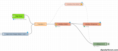
@ohsolar Here is a small writeup I did on using NodeRed with Schnieder.
My example if for having multiple time of use windows (which the firmware doesn't support) but, you could re-use 95% of it.
The timers, the Modbus interface, and things like that would be identical. you'd just need to find the modbus address for forcing the charge state to "bulk" or "off", so.. hopefully it'd get you a good bit of the way towards your goal.
That's a nice writeup. I was thinking to just fetch the value before configuring the whole thing since I did not follow parts of it. I need to spend some more time..@ohsolar Here is a small writeup I did on using NodeRed with Schnieder.
My example if for having multiple time of use windows (which the firmware doesn't support) but, you could re-use 95% of it.
The timers, the Modbus interface, and things like that would be identical. you'd just need to find the modbus address for forcing the charge state to "bulk" or "off", so.. hopefully it'd get you a good bit of the way towards your goal.
So I found these. I guess I have to do 0x0165 minus 1 (357 - 1 = 356 dec) to force charge it.


on node, victron was easy
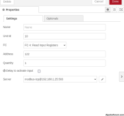
ok, I would like to read in the charger status first just to see if it returns the value. From your post is the format of the msg.payload the same I have to use? I was thinking to use the 'trigger' module to just hard code the message just to see how it works. What array values can I usemsg.payload = {
"values" : [what, goes, here] ,
"fc" : 16,
"unitid" : 10,
"address" : 122 (7B = 123 - 1) for charger status
"quantity" : is this 1?
}
this is fun

Last edited:
Getting some error..


Injecting 356 :

var gsv = msg.payload;
var buf = Buffer.alloc(4);
buf.writeInt32BE(gsv)
var values = [(buf[0]*256 + buf[1]), (buf[2]*256) + buf[3]]
msg.payload = {
"value": values,
"fc": 16,
"unitid" : 10,
"address" : 356,
'quantity' : 1
}
return msg;
Injecting 356 :
var gsv = msg.payload;
var buf = Buffer.alloc(4);
buf.writeInt32BE(gsv)
var values = [(buf[0]*256 + buf[1]), (buf[2]*256) + buf[3]]
msg.payload = {
"value": values,
"fc": 16,
"unitid" : 10,
"address" : 356,
'quantity' : 1
}
return msg;
Attachments
Last edited:
is this the correct document for insight/xw pro?
 onedrive.live.com
503-0246-01-01_RevA.4_Modbus_Map_Conext_XW_Device.pdf
n2aws
Solar Addict
- Joined
- Oct 24, 2022
- Messages
- 690
Not sure, I downloaded it directly from Schnieder, under the Technical publications for the insight home device. it's a zipfile of modbus maps for the whole ecosystem.is this the correct document for insight/xw pro?
503-0246-01-01_RevA.4_Modbus_Map_Conext_XW_Device.pdf
As for your node-red setup.. You'll want to use the mobus-flex-getter, since you are trying to get a value, not write a new value.
This is what I ended up with:


quantity is 1, since it's a uint16, not a uint32 (I mention this in my writeup)
I also mention, if you are writing a unint16, you don't need to do all of the buffer manipulation, and inclduded a function code example to show a 16bit write
Not sure, I downloaded it directly from Schnieder, under the Technical publications for the insight home device. it's a zipfile of modbus maps for the whole ecosystem.
As for your node-red setup.. You'll want to use the mobus-flex-getter, since you are trying to get a value, not write a new value.
This is what I ended up with:
View attachment 177072
View attachment 177073
quantity is 1, since it's a uint16, not a uint32 (I mention this in my writeup)
I also mention, if you are writing a unint16, you don't need to do all of the buffer manipulation, and inclduded a function code example to show a 16bit write
Thanks for being patient @n2aws. I am getting some good results now and am able to put the inverter in standby/operating and also change the bulk/float states. Rereading the article helped. Had to figure out the fc things but was in your write-up. I can see the status change on the insight but it doesn't actually do it. Some setting might be off (maybe V or SOC)..more debug
thank you

400bird
Solar Wizard
Just in case you weren't aware, even when you command bulk charge through modbus all the other parameters are still obeyed. For example, charge block timers.I can see the status change on the insight but it doesn't actually do it. Some setting might be off (maybe V or SOC)..more debug
What kinda works
set recharge soc : 99%
enable/disable charger
need to take a break but need to follow n2aws article more..later;-)
"- In my environment, I have all the other settings how I want them. So, for this example, we're *only* going to be changing the grid support voltage. During "peak" periods, I set it to 51v. During offpeak, I set it to 65v (which enables enhanced grid support mode. This will prioritize charging the batteries from solar.. and will only go back to supporting loads or backfeeding the grid once the Schnieder SCC's get to "absorb" and "float" stages. You may need to expand on this example if you have multiple settings you want to change."
Last edited:

400bird
Solar Wizard
Glad you got it working! That's good news.
Refinement is something I worked on for a long while, and I'm sure there's still room for improvement.
What is the Modbus Response node?
Refinement is something I worked on for a long while, and I'm sure there's still room for improvement.
What is the Modbus Response node?
I haven't used it but I am thinking it shows the responses from the request. I just copied from originalGlad you got it working! That's good news.
Refinement is something I worked on for a long while, and I'm sure there's still room for improvement.
What is the Modbus Response node?
The error on the below request shows up in the response obj(i think) but not sure how it gets display in the debug. @n2aws might know

Modbus-Response
Node to show response or response length from second output of Modbus Read/Write/Getter nodes in status.
Show-Max-Register is the border from where the node only shows, how many data are in response array.
That node is just to get some information and it is not necessary to work with Modbus Read/Write/Getter nodes.
If the Modbus Read/Write/Getter sends data very quick, don't use this node to much, please.
n2aws
Solar Addict
- Joined
- Oct 24, 2022
- Messages
- 690
It shows the response of the getter/writer action directly in the pallette. Allows you to see if the values are what you expected without needing to go review the debug tab. More of a "nice to have" IMO, than anything. At least, for what we are doing.What is the Modbus Response node?
Debug messages show up on the lefthand column, when you click on the debug tab.The error on the below request shows up in the response obj(i think) but not sure how it gets display in the debug. @n2aws might know


Similar threads
- Replies
- 2
- Views
- 128
- Replies
- 13
- Views
- 527
- Replies
- 30
- Views
- 1K