diy solar

diy solar

Seplos upright case build finished today !

MisterB1959

Solar Enthusiast
Joined
Oct 22, 2022
Messages
355
just finished building my 16 x 280Ah EVE cells in an upright mobile case from Seplos, i had a few minor issues, but sorted them out and am really pleased with the end result

IMG_20230624_141934.jpg


The instructions didnt quite 'fit' the reality, or the parts i received, but a few tweaks and its ready to go. if anyone is considering one i can send a fully detailed document on how i did it, NOT to be confused with 'how to do it; - its how i did it and it worked for me !
 
How are the cells arranged in that case? I saw it and was intrigued…

Do you have any photos of the inside?

Two other questions
1. Would the case be water tight or water resistant?
2. Is the any way to fasten it down - so it doesn’t tip over?

Thanks
 
Last edited:
The instructions included with the horizontal version were terrible too. Thankfully there are multiple build videos on YouTube.
 
@Rocketman
@Alkaline
@niktak11
@Tulex


as requested - i will have to post this in parts due to the size if the document ....


Seplos Mason Mobile Home Storage Battery Case

Please note, although i had a couple of issues that i needed to resolve, i am more than happy with the case. It has a sleek and modern appearance with a small footpint, the fact that it is mobile and ‘easy’ to manoeuvre whilst still being stable made it perfect for the location i had chosen to install it into.
I might not have all the correct terminology to describe all the part/bits/bobs, but hopefully you will understand what i am referring to !

I would highly recommend this casing and intend to buy another in the near future.


The case is supplied in two packages, one being the case itself, the other contains all the connecting accessories, screws and fixings.

1 Remove the case from its packaging. There are two options in building the battery, you can either lay the case on its back or build it in the upright position. I chose to build it in the upright position due to the weight of having to then lift it if i built it on its back. After adding the cells, i found it was difficult to actually knock it over, which i was concerned about whilst building it.

The case itself is virtually pre assembled, although i needed to remove parts of the assembly as I will describe later.


mqAyb2AJGozYAtA5GIYn0EAilkElgGHlWDnOXdlHyvgs9KYW5czL4Rq_zyNZKXumJOHjkEobjlW4DhaFjjtSdCN7OiGBjiW9h4YaxZ_CyfWARfmxLQrdRe6cmWkCd0hGLTqhDml802nCHuJncKCzMnk


2 remove the front of the case, The casing is held together by machine screws with a 3mm hex key head, Not all the screws have been used for the pre assembly stage, i assume to make it a little easier.

BLh6mYq7aTo34rKJ4dNlFpbLeZaDANtsHRsceSFCTT3374OKb-kYY8RDrZTRSHclAVd62_6XpLZb8vLC_xhZy-XBKJcDO__IO4k1HBd3Syctxw-XfKDMlhG1LJ2W1UXdEYWmTdqYbnvOszJGDNpO2As


zK5LlvZjmaPiwmO405UYCpqZ6jKnaF_2scZ61TXeA9W9lQDEx3I4QxBbRmTC_qZNBOR4QL0EN9vri1iihqudAKUdyAiR37M9G9YFmOkHxVENdE0359yCRP7vqdXjbO0rN8H_aqH1Nqq_652EeG9Etoc


Inside view after front cover removal. The linings for the case are supplied loose along with foam backings for the cells and reverse of the busbars

3 Remove the two BMS busbars, They are each secured by four small bolts that can be released using a phillips screwdriver, place the busbars in a safe place. They are wrapped in cellophane to protect them. The busbars have slots in them, rather than just holes. That is important as it allows for some leeway when the cells are fitted.


xMEgSlrn2DjOWPfimOU47ZFeqg14mHWXNtTPnzHQmcR9tzxkJGiYaFvWFikV0m2ey0TzqFfJ_Alrr3OaAEqLwgpZJhx7WfO39VJaeX5uxjYii12t60PXAI-4VjJfr3De-zmxBIoVNN9uU-CIMF2Vw68
 
Last edited:
4 Before fitting the case linings, it is important to check the cells actually fit! I used 280Ah EVE Grade A cells from Fogstar. I installed the linings prior to checking the cells fitted snugly enough to provide some compression.
After placing the first column of cells it was clear that there would be no compression of the cells or that they would be held in place by the case.

rSGIQTwP2yxpAOsa0DME-i-sspGOpymjHd-CsfACYkTFC24QuO7yicbjVidUATV6eJjv38vvfRbDIfbUdS98wrOnfyw-MpAdfVhzy1plHNbNoWMYOk-f-31rtJqJfaznsjs0LX2sIZtO9fvbkiG-5hU


You can see clearly that there is a gap between the top of the cells and the ‘top plate’. I measured that gap to be 14mm. I felt uncomfortable as i didnt feel the cells would be secure and that the gap would potentially allow cells to expand and possibly degrade.

I also realised that due to the construction of the case, the bottom cells were only in contact with the frame of the case along their outer edges. This also concerned me as they may have expanded in the unsupported area, a term i refer to as ‘bellying out’ - not a technical term but my explanation!!

V9mNZCJxrodO4H8OfkH8RIeRzWrgEzkq2IqjFmeZu1kdGDITNBuVJFwg96m52W1vmUFhkbW3XkV_At4hO3967NQ7qsB1gI_D-v1timMZtmPuPVhWrO7As_XL5o4ZRqbjk6f4E7OxHOeHQWzAx1pLShA

This photo shows the bottom frame onto which the cells would rest
 
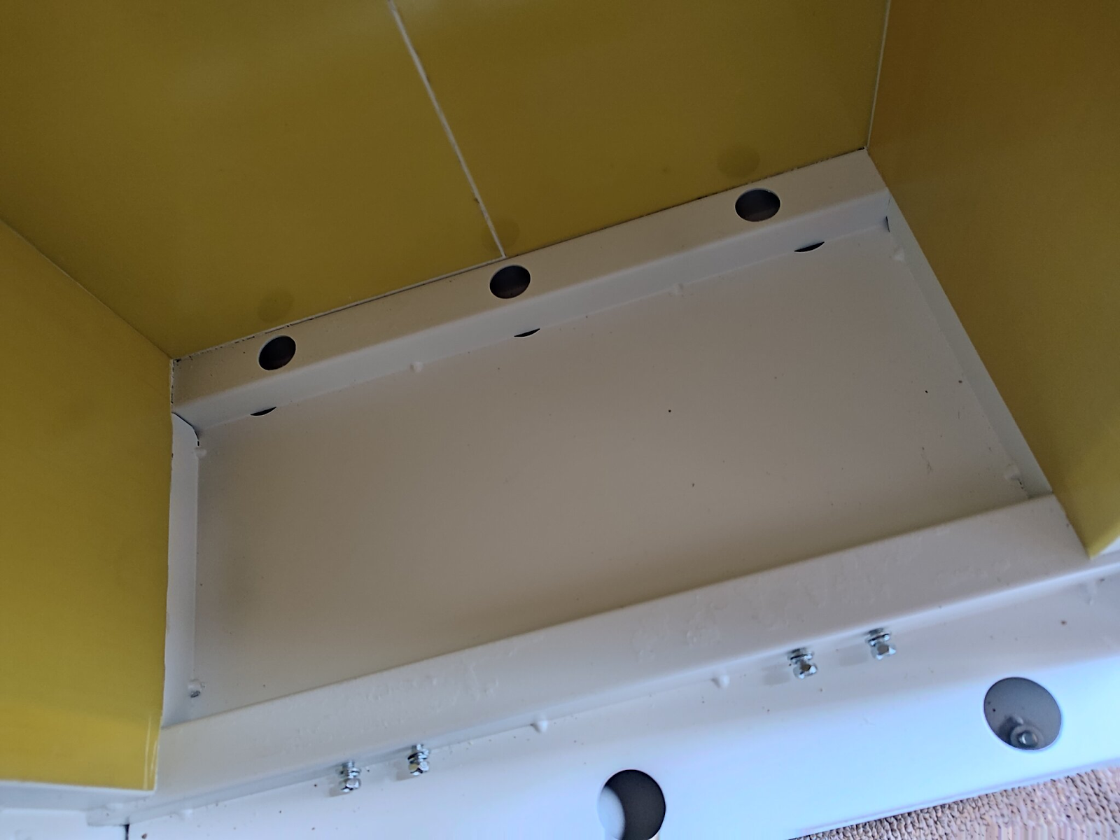
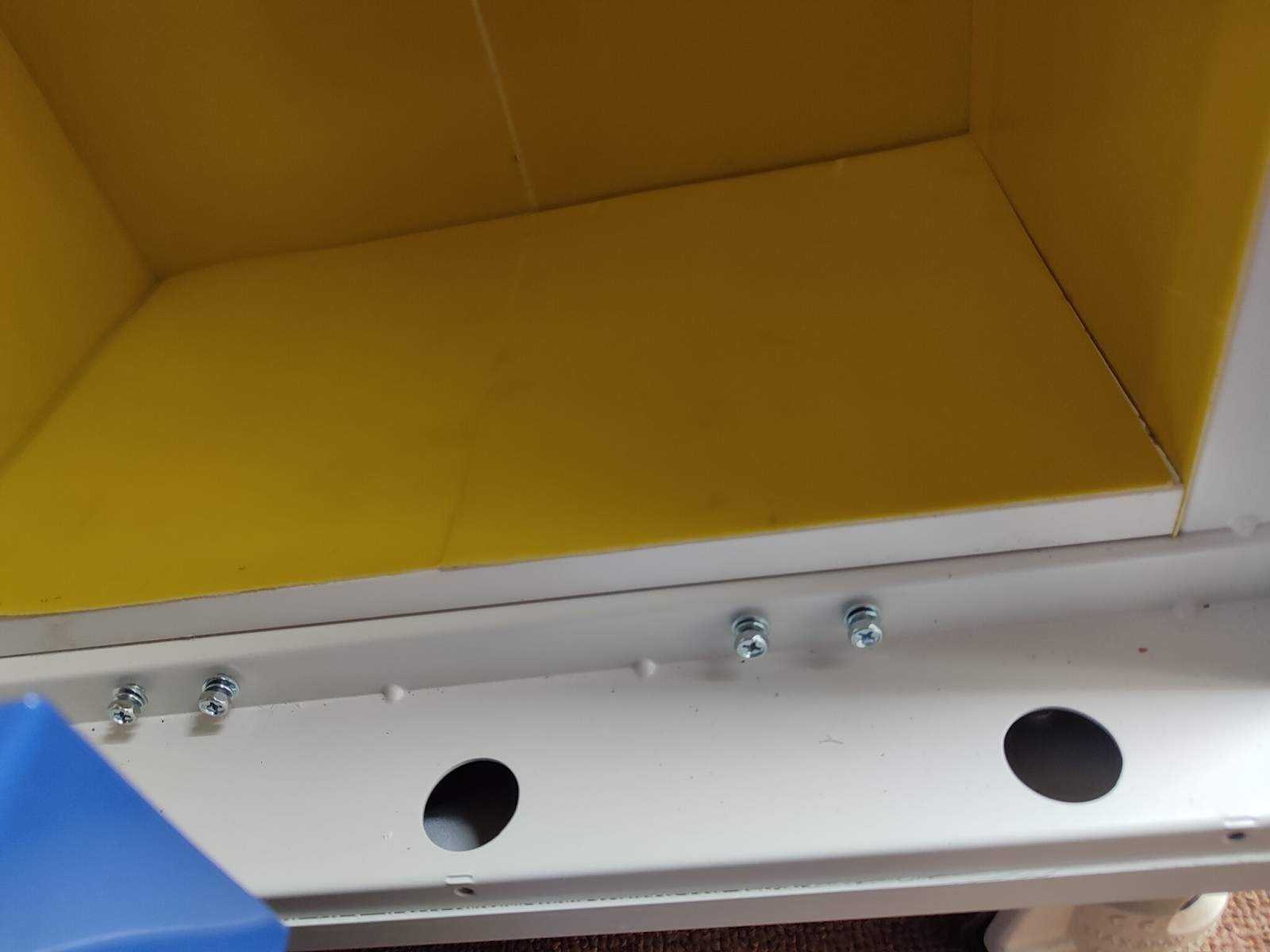
5 Supplied with the case were these packings/shims

h1DzI4rslpbnAWVEKnTSyd9f11ZxCNaoOOAuBScYlGYKoP8O6tQY9k6mbk42V99vx1YvUH42rsYbeGoIslmAXmoenGiQJh5Tenx8xNsCvXOgGEsscspZi4WFyyUOXpRE4_u-me-gmihbCRo-R8q-RPk


Perhaps they are to allow for different cell heights and are used to pack up from the bottom? They cant be to be fitted in between the cells as the cells would then not fit. I decided not to use them as packings from the bottom, as it wouldnt have stopped the potential ‘bellying out’.

I need to add though, that perhaps i was overthinking things, Im sure the cases have been ‘designed to death’ and tested by technicians etc

Notwithstanding the above comment, i decided to adopt a different method to ensure compression of the cells.

I added a 16mm piece of melamine and placed it over the bottom rails and added the case lining material onto the melamine surface

rHhJFzAkIQTzTmnrvp_Ni1pF2C4kxbOJ0rP4GIjy08ytvGl8576l2WiN9v3kJUaqxWeeD7lJ2rXG7wvFBNLbVj868jv_ShqkWY5cUYwqZfIXUMbNRrcU28ERFM9o35zGBM6t51zW4NYQ3wRQw5mZekg


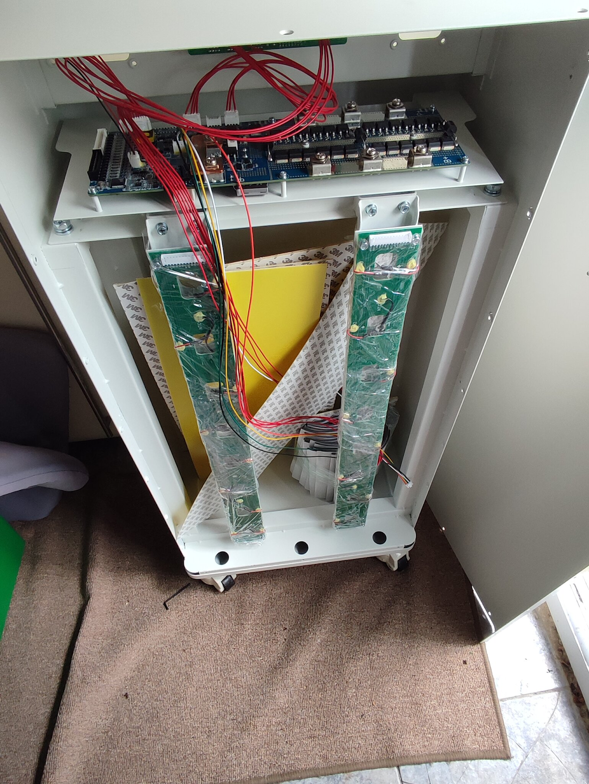
6 Before replacing the cells, I needed to remove the top of the casing, and the BMS (which comes ready installed onto a bracket) and also the top plate of the casing which would allow for it to be used for compression of the cells and hold them in place.

I needed to use a long reach phillips head screwdriver to release the fixings at the rear of the BMS bracket. The BMS bracket and top of the case were removed together as there were a few electrical connections holding them together. I decided to leave those connections in situ. I just laid the BMS plate and top of the casing on top of the case itself, making sure of course that i was secure and couldnt fall or become damaged.


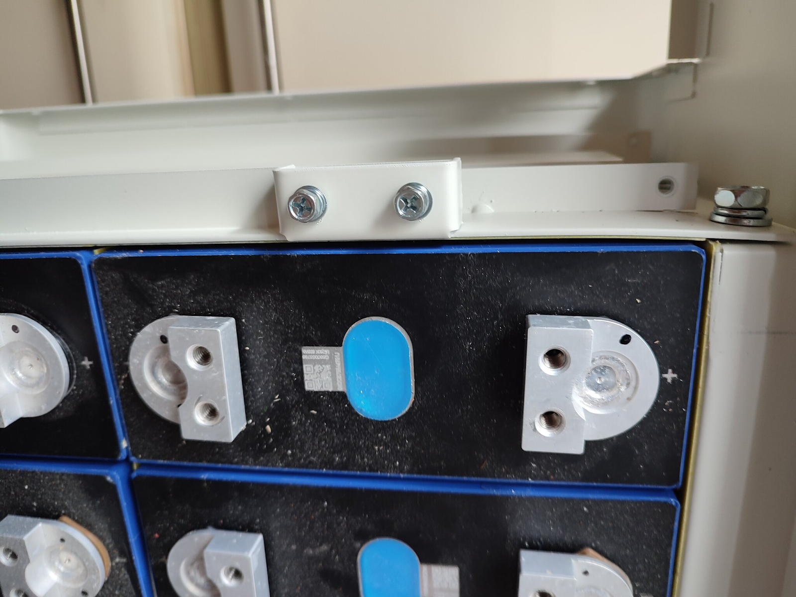
This next photo shows the cells in place and top plate adding some compression (remember there are foam pads between each cell, so its not a massive amount of compression). If you wanted a greater amount of compression, you could use something larger than 16mm melamine, but then there is a chance you would need to alter the BMS busbars.

fnD0GFw1DPIZesycRfbW1Kgkjb3GrwPXrObeDQ78rtwaZerxzDhNNtBxYjRTCDbsDNNsVp53FNmAOJocZMqJMv4RiuTSxcYjgIe_xulxa_xXDi3PDUy5-uffaZ8uU6bOtsVTgWUYfjorfigey5fzcIQ


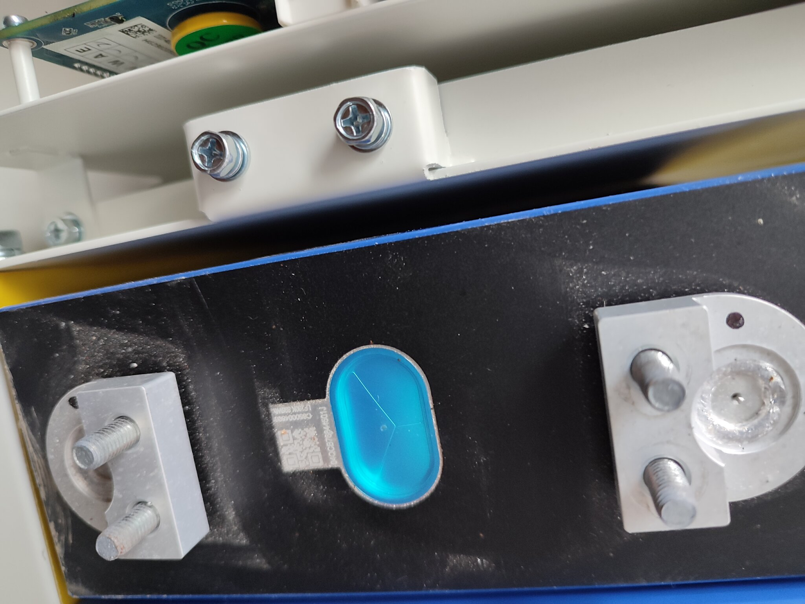
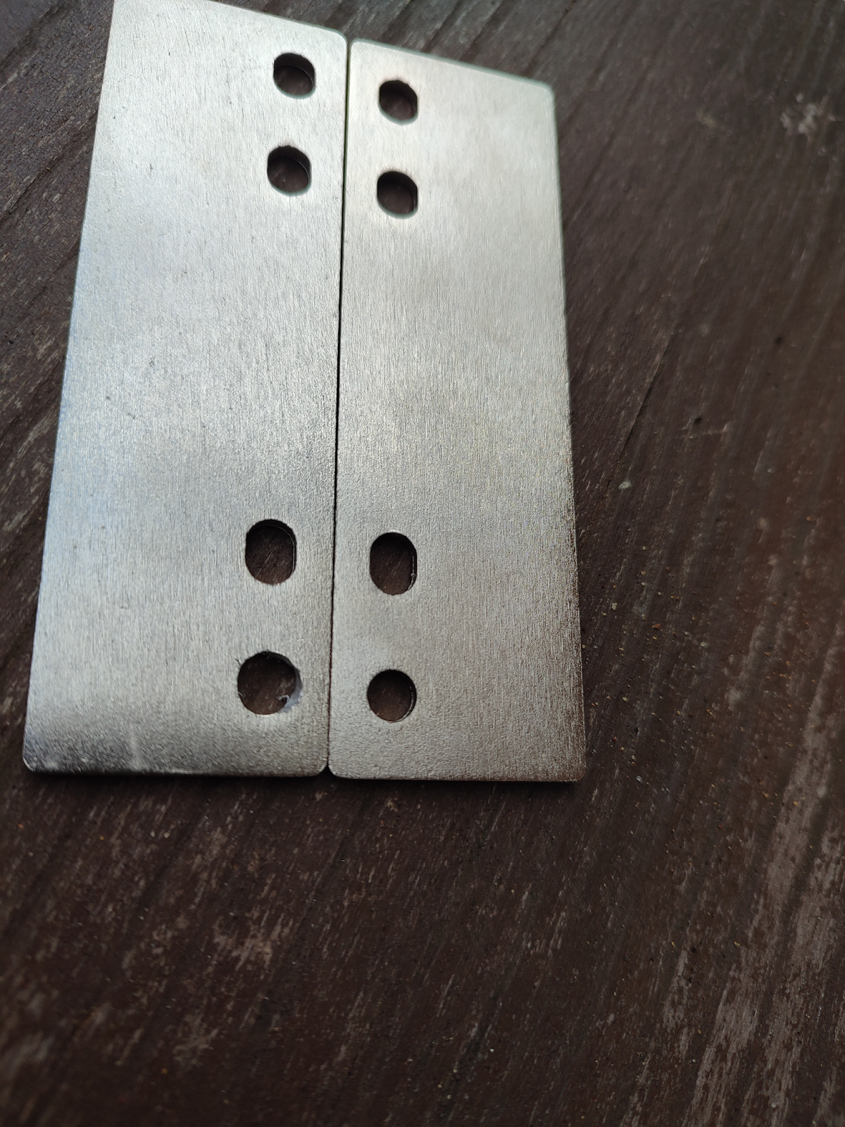
Which, from the next photograph, you can see that they fit perfectly, however the busbars between the cells didnt! There were about 6 busbars that i needed to alter so that they fitted. The busbars have four holes, three of which are elongated, for some reason the last hole isnt? I found by elongating that hole in the direction of the other holes, i could make them fit. If all the holes were elongated it would have been simple and would compensate for compression of the cells.

yE9japStQhKIV-Ew5uTYfDo_nZEPicPeP3TYH9vkrPpWBOwEmEtbhMn66xbIHAzvMOtxyKhWF63Jb688kECFVTlQQEiq0fwWBb6Y-J0-jaZuIymTd0k7aIud0ZZzW4co3eFoJ_gGuJiK0bfCsgX5Gsc


It is important to follow the sequence of attaching the BMS busbar connections to the cells, a couple of the connecting wires are coded red, but actually fit onto a cell negative connection. The connecting wires are clearly marked on the BMS busbar with a + or a - , so all you need to make sure is that each cell has a + connection and you make sure that those with a - marking on the BMS busbar go to a negative connection on a cell. Once youve got it in place and start to add the busbars between the cells it becomes self explanatory as the wires themselves are not long enough to cause any real confusion.


Before connecting the cells together i added the BMS busbars, having removed the cellophane coverings. But before doing so i had a ‘dry fit’ just to make sure it was all going together properly.


KvfJyhcvTpZl9PThhNnMuRQuty_TlHrJABfTfd-2uWvzkZoDQtfYV8nUsRKb9dq7IQGmhjdw5vsb0dCXQ-wAEEZX3oknK2K7OcXe3PygnG2JXC1wOvn6uUn1NGILOrq4q1aJvr7MFLo9wj9aWb0Wj9g


7 I actually reinstalled the top of the case and the BMS at this point, to make sure it all fitted back together again, but on reflection it made sense to add the connections to the BMS when they were easily accessible, so i removed the top of the case and BMS on its bracket again. I would suggest that before replacing the BMS bracket and top of the case that you add all the connections at this stage.


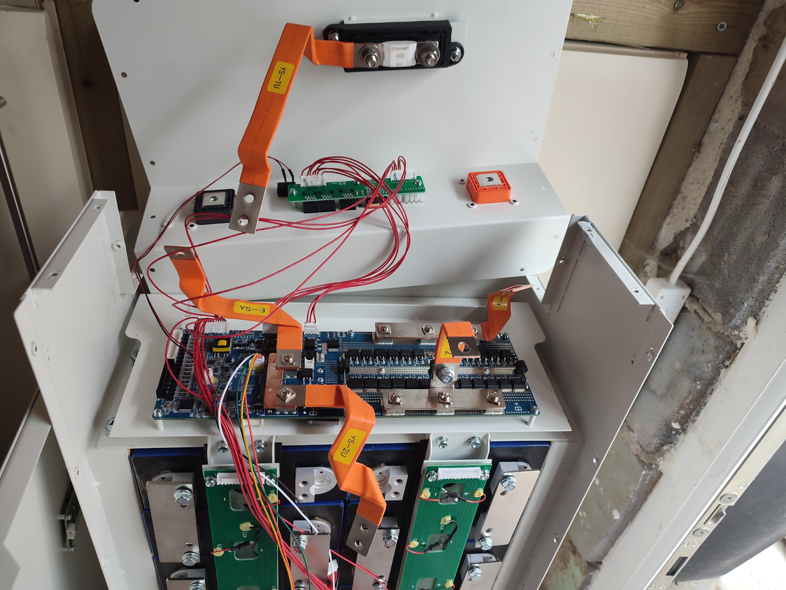
8 The main connections from the battery and to the power outlets to/from the BMS are not as shown on the Seplos instructions. They are also numbered differently. The next photo shows the connecting strips/ribbons connected in the correct places. You need to install the battery terminals and fuse holder

kJoGoBx2v3hqrhlEa2wYNvh5QPz7Jr8869eiHYRw6tE2SpsComO6YgUWGanT9hFHF2u3lr5iBknhSFetkiEClLZaJTNdsgUQI6bK4_WM7TCMQI44Q78g7nhdiv_CJB6fgz91OTjj_CasTD_PIy3Ubkg


The fuse holder cover just pulls off, its tight but just pull it off. You will need to cut the plastic cover for the fuse holder to allow for the connections to the fuse. You need to cut one side and one end as shown

zfVud2-09l8Red4b0rvpDaUvLlXlbHB_Z2oR0n2HNcmbDBrTvGxlD-mUY4qM_lsy19qEvDWq6vZTjFl9fVU5J5MnP3nI2oNupaxKKPie9fR7w6Aelcqru873FODQ0cDknwfG2nOYAI46py0QDJnihSY


IFa9uS8axz8B1p_1k9p3HA1jlEK4As6sgv0Y67iGu5FggUX0Dw6fduRBe3sUXxQuRmvr7q7nE-cU2tDO9SGYWEQL8nmmWPFW7aWSTyc4eExgYxpuMu-6y4pVE5THi57X3ktGLTBBYAjgyCMcOAuWKc8


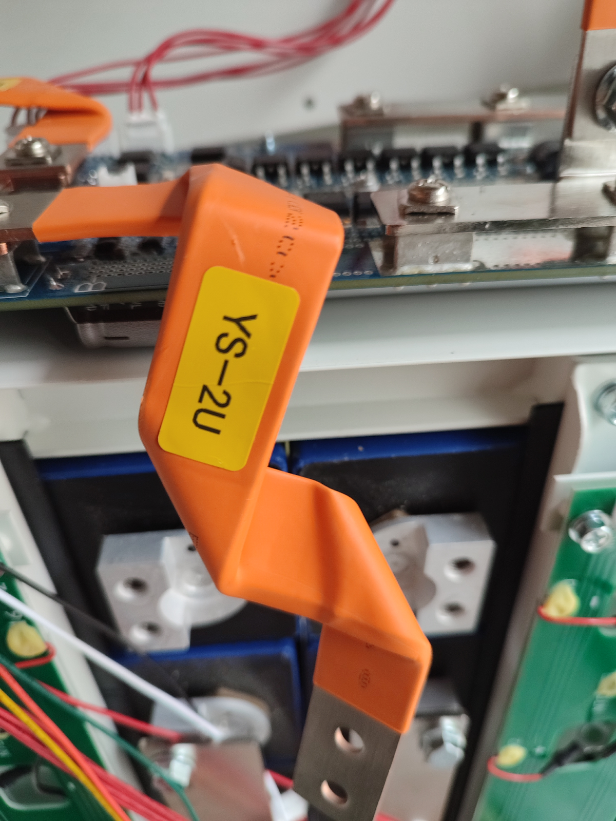
And close up photos showing the ribbon/main connections

XAagAD5iEFw8b9rBBsT1omW4PlpcVIuUdjtdG3_VcXPtbWMklMD3ogmmTRX-oWPJdlA7VWs30r5azylb6XPMGPvIYALuedM_WKTvzafKxABqf1ds7IGdR5qp2S9P_2RxiCFz0fp5raUzBMN15IhEcd0


-MpIiFzencyANLBQdERZsKcnzJdgKrfE3qjY58BFy9mc7VVQAZHngvh0K1dpRqvMg4U3hgQghBdL1yaVdhbPtxTsiLyNozY2ucLPADPAb4sm7Z7_GuTAJplOf9h1BbBWV7sFICLyWJEGtO8NAF6Mn1U


hHH4rbS42kHz9DIma4PWnr2NwMIBBeuQbhIvycUktdW_N48czz1OWFFjeRK0nyTLpDwr9BXA-mKhczn-Wx2XuJA_VgHW7Mk4YAEnQn5qlNN8aopxlkY3zLcP1UfYicgZY3460QcRJYKLuL-HLGvPj3s


9 The final part of the internal assembly was to ensure all connections were tight and to connect the BMS to the BMS busbars. The prewired looms are different in that one of them has a black connector to go the BMS and the other has a white connector (both have the same connectors at the other end)
The Black connector loom fits onto BMS at the connection nearest the front and the white one to the rear.

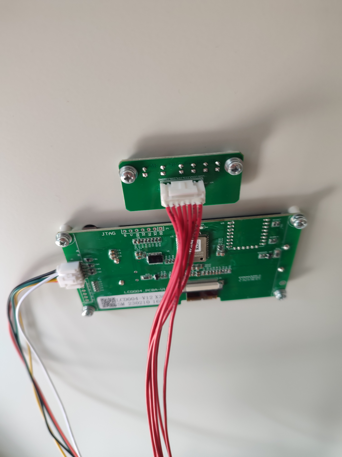
10 Before replacing the front you will need to connect the cables, already connected to the bms and back control panel when it arrived, to the front display,

WRqVa22fQGq-2w8Bm_dnH7FRjxDCGLIZiNxkwPqGIR_3mpsenodVsiOqDS3wFdPfzwyU3S2ot14E2xS9ODygpMPLStxM8k5LA1dPt2779HGvRqI-GNJQHq2hCU1oDz1SxArdNbwWTFIlGpS8vgfoSEE


10 switch on the battery at the rear of the case to test and the front display should light up
 
Fell in love with this Case,
Nice detailed explanation btw.

Meanwhile, Do you/anyone have a say regarding the placement of the batteries?
I mean, they all lay ontop of each other, while the First Battery (on each side) bears the weight of the remaining 7s
Is that safe?
Would it bring any complications in the future?
 
That's still less than the recommended compression force I believe so should be perfectly fine
 
I believe it was determined that the compression Eve used in testing was 12psi.
Batteries weigh 12.12 lbs each with a surface area of 53.6 square inches. Stack of 8 batteries, bottom battery would then have 1.58 psi on it.
 
Damn, my 3x Mason kits will be here in about a week or so, wishing I got the upright ones, as they would fit my space better. Oh well. Live and learn.

Happy to see the internals and someone is happy with them though!
 
I believe it was determined that the compression Eve used in testing was 12psi.
Batteries weigh 12.12 lbs each with a surface area of 53.6 square inches. Stack of 8 batteries, bottom battery would then have 1.58 psi on it.
just to confirm that the compression is basically just holding the cells together, i didnt fancy leaving the large 15mm gap for the cells to expand into. i think the case, as is, also takes 304Ah cells which is perhaps why there is some leeway in the spaces for cell sizes?

For those in the UK, i got my cells and case from Fogstar UK and they are currently offering what i think is a pretty good deal of 16 EVE grade A and the upright case for £2396 inc delivery (not sure how that compares to US/Canada/Australia prices but its pretty keen for the UK) . Not sure i can/should post a link as it might be seen as advertising, so i will leave anyone interested to check it out themselves.

i am very tempted to buy another one to double my storage !
 
Last edited:
Nice write up, any details on how you balanced the cells? Curious to know which invertor you are using? Aware the Sunsynk works well with Seplos BMS's
 
Nice write up, any details on how you balanced the cells? Curious to know which invertor you are using? Aware the Sunsynk works well with Seplos BMS's
Thanks. I top balanced the cells twice before doing the case build using a 12v adjustable power supply.
I am using a Sofar ME3000SP inverter as I have my PV working through a separate inverter. The reason for this is that it has been installed for seven years and we receive quite a decent Feed in Tariff. If I altered that system I would lose those payments.
I am considering adding another 14.3kw battery and am just waiting for Candice (Candice@seplos.com) to get back to me with confirmation of how to connect the two BMS's together.
 
I am considering adding another 14.3kw battery and am just waiting for Candice (Candice@seplos.com) to get back to me with confirmation of how to connect the two BMS's together.
If I remember correctly the YouTube Chanel Andy’s Off-Grid Garage hooked up a couple of Seplos BMS’s together. It was something about needing a certain revision letter of the BMS.

Good Luck
 
Nice write up, any details on how you balanced the cells? Curious to know which invertor you are using? Aware the Sunsynk works well with Seplos BMS's
As does deye/sol-ark, most major inverter brands are supported, especially by the newest version ( V3)

Victron somewhat, but they have a slightly different canbus implementation, which sometimes gives strange result with the 10c and 10e version, they seemed to have fixed that in the V3 version, but have had my hands on that
 
If I remember correctly the YouTube Chanel Andy’s Off-Grid Garage hooked up a couple of Seplos BMS’s together. It was something about needing a certain revision letter of the BMS.

Good Luck
thanks, its a simple case of just linking the batteries together

This is the response i received from Candice@seplos.com

ChwX2MIOTI.jpg

The two battery packs are connected in parallel, you just need to use the RJ45 connector to connect them in parallel to come, here are examples of other products that I hope will help you.
 
What's your opinion on the fuses used in these units? 400 amps seems a bit over kill no?
  • I suppose I would imagine a 225-250A fuse at most on a 200A BMS? (or is it a 400A fuse because the peak/surge amps on the BMS is likely 350A?)
 
Back
Top