diy solar

diy solar

Should I test every single Cell I received and other doubts/questions after Leaking Cell

silverstone

Solar Enthusiast
Joined
May 3, 2022
Messages
1,041
I FINALLY managed to put all cells inside my battery box and ... well ... a few things went wrong (again).
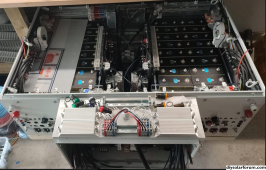
1693803341077.png
I'm kinda disappointed with the result really. The cost was quite high, the quality so-so and of course, for all the extra features I wanted such as contactor, light signaling, extra signal cables for feedbacks & 5V/24V PSU etc, there is NO PLACE TO PROPERLY ROUTE the cables. And every device on the side DIN rail cannot have anything "output" in the lower hole because it's in contact with the cells / cover. An absolute nightmare.

Might as well have bought a ready-to-go battery. Learned something along the way, but I think this was NOT the result I wanted :( . Got the cost without the benefit really.

Now at least the cells are in and squeezed lightly. More than handtight (couldn't even turn the nut by hand, would have left 20mm of gap ! - yeah 20 mm !), but "tightened" I'd say reasonably, then backed off a few nut-turns (M10 - pitch is ... 1.75 mm ?). Sometimes you can pull out the yellow spacer and sometimes you cannot, that kinda tight. But cells are NOT too loose by any means. So they may have maybe 2-5 mm gap ACROSS 8 cells at around 50% SOC.

Now the question ... should I test every single of them ? They should be at around 50% SOC (3.26V - 3.29V) right now. With the EBC-A40L I can charge & discharge with 40A ... So theoretically that would be 280 Ah x (100% charge + 50% discharge) / 40 A = 10.5 hours / cell. Times 32 cells = 336 hours = 14 days full time ! More likely it's going to be 3 weeks. Not sure I'd like to wait that long to be honest :unsure:.


1693803225103.png


Cells were bought from Docanpower if that matters. They have been in long term storage for a while and no, unfortunately I didn't cycle them yet. Couldn't even move in my garage in the meantime.

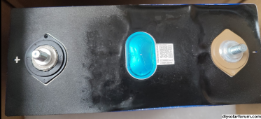
Actually I discovered yesterday that ***** ... one cell from the second batch that I got delivered from Docanpower had suffered an electrolyte leakage probably during transport (I only noticed it now several months later when I *could* open the packages).
1693803866639.png

I promply contacted Docanpower about it. Let's see how they react.

Thankfully I had one cell as spare and put that in instead, even though it was from the first batch, so a bit older ....


By the way, how do you evaluate the status of the pressure relief vent/seal?
Some look "clean & tidy" (just the gold dot in the middle with the 3 weak spots the blow over pressure), some have "slight" bleeding (black color) around the middle gold dot, .... They are all different :rolleyes:.
 
Last edited:
If there is any question about leaking electrolyte, I wouldn't put that cell into service.

I would have top balanced the cells prior to installing them. You compression fixture sounds a little loose to me. I can pick up my battery by the fixture and nothing falls out the bottom.
 
If there is any question about leaking electrolyte, I wouldn't put that cell into service.

I would have top balanced the cells prior to installing them. You compression fixture sounds a little loose to me. I can pick up my battery by the fixture and nothing falls out the bottom.
If needs to be *that* tight? The cella are approx at 50% SOC right now. I didn't top balance prior to installing them in the fixture because I didn't want them to bloat.

What @upnorthandpersonal told me was to "hand tight" the nuts. I even used the Wrench since I couldn't manage by hand.

About the leakage docanpower told me that it's probably just air, water and humidity, and to remove the black label and see if I can get it cleaned. Sounds fishy to me...
 
As I recall, I tightened the nuts on my 1/4" threaded rod to 12 inch pounds. Good and snug, but I wouldn't call that tight. If you have separator sheets that can be pulled out then I would say it isn't tight enough. My cells are deployed in a mobile environment. Movement of cells would be a bad thing.

I suspect that Docan will tell you whatever they can to get you to go away.
Well yes and to be honest I'm not going tge next cells from them if they try to wash the problem off, that's for sure.

Not that I trust warranties provided by LLC Danish Company on Chinese batteries. If something goes south they'll also file for bankruptcy and not honor any warranty.

Difficult to trust anything these days ?
 
Mine are hand-tight, but I can't pull the separator sheets from them. I should measure the torque, but I don't know when I will manage - things are hectic...
 
I am working right now on a prototype pack so i am all over everything about diy lifepo4 batteries. What is exactly this battery box? Did you make it yourself?
 
How does it smell? If it's electrolyte, it usually smells really bad and you can't stand being close to it.
Smells of absolutely nothing i'd say.

Dont bother measuring the Torque. With the Wrench when I tightened I would guess I felt some resistance (before I backed down), probably something like 3-4 NM.

I cannot measure Torque with the Wrench anyway, only screwdriver and ratchet.
 
I am working right now on a prototype pack so i am all over everything about diy lifepo4 batteries. What is exactly this battery box? Did you make it yourself?
Yes, it's something I made. But to be honest the cost is quite high for the metal parts, comparable to am off the shelf solution (bslbat, Rosen) that we could get here. Got more custom components though and not the cheapest fuse/disconnector on the Chinese market ?
 
Yes, it's something I made. But to be honest the cost is quite high for the metal parts, comparable to am off the shelf solution (bslbat, Rosen) that we could get here. Got more custom components though and not the cheapest fuse/disconnector on the Chinese market ?
wow, pardon my french but it looks like a fustercluck for a newbie like me. What are all those wires and stuff doing? There is a million wires going everywhere and the busbars aint even there yet. I dont understand even half of it. I am trying to design a battery bank myself, could you pls list some of the functionalities that you wanted to implement here?
 
See i am just thinking about individual 16 cells packs each one with compression, t fuse, dc breaker, jk bms with its button and terminals. Good to 200a continuous discharge. I discarded the idea of putting a screen on it so i have more space. I cant think about any other relevant function to put on it. Maybe a heater but that one is going to go inside the enclosure so it doest belong to each pack. A see a million things on yours, could you explain some of it pls?
eambatterypack.jpg
 
See i am just thinking about individual 16 cells packs each one with compression, t fuse, dc breaker, jk bms with its button and terminals. Good to 200a continuous discharge. I discarded the idea of putting a screen on it so i have more space. I cant think about any other relevant function to put on it. Maybe a heater but that one is going to go inside the enclosure so it doest belong to each pack. A see a million things on yours, could you explain some of it pls?
View attachment 166349
Maybe mine is more industrial-like.

Basically you also need a precharge circuit with resistors (plus fuses, switch / push button, optional contactor). Otherwise what might happen (unless your inverter precharge first or you habe a smaller charger in parallel always connected to ensure a minimum voltage on the inverter terminals) you will habe a (potentially) HUGE current spike when you close your main breaker / switch. This is because you're charging your DC capacitor of the inverter (on the LV side) to say ~54 V. Without precharge resistor you could get up to 10 kA, drastically reducing lifetime of capacitors and fuses, potentially tripping fuse/breaker and blowing caps up after repeated attempt. The resistor for precharge slows the start down (I put 2*4.7 Ohm in series so approx 10Apeak during precharge).

With a precharge network, things get a bit more complicated, depending if you want to precharge both pôles or if thé resistor sits only across plus and output_plus for instance.
I have:
- BUSBAR_BAT_POS which is battery busbar after fuse (aR fuse, could also be class t...) and Breaker for positive pole
- BUSBAR_BAT_NEG which is battery busbar after fuse (aR fuse, could also be class t...) and Breaker
- BUSBAR_BMS_NEG which is after the bms (where you will connect your inverter)
- WAGO_OUTPUT_POS which is after the precharge resistor network and the main switch disconnector / contactor
- WAGO_OUTPUT_NEG which is after the precharge resistor network and the main switch disconnector / contactor

If you always remember you could get away with a pushbutton and precharge resistor...

I then have several outputs breakers, mainly for tinkering, local output, aux output. Can also be used to attach eg battery charger or in this case to put something temporary in place.
 
This is an overview of my schematic if interested

I'm still not 100% sure if I will use the contactor+switch variant or just the switch variant. With a 4 pole switch disconnector i can always change by moving the output cable from one set of poles to the other.

Precharge network both on battery and inverter side. Not both are really needed, but with several batteries and several inverters you have several possible combinations to cover. Easier to prepare for all use cases ...

I guess many people think this is overkill and just go away with a resistor hooked up to a small pushbutton or something.

Whatever way you do it, ensure you do NOT close your battery breaker/switch on a short-circuit. And a capacitor at 0V behaves like a short-circuit (for a short time).

I suggest to also hook up a smoke detector to a shunt trip unit for your breaker. In this way if things go south, you trip the whole battery, no matter comunication with inverter or lack thereof.
 

Attachments

  • Battery_Schematic_Overview.pdf
    2.3 MB · Views: 11
Last edited:
See i am just thinking about individual 16 cells packs each one with compression, t fuse, dc breaker, jk bms with its button and terminals. Good to 200a continuous discharge. I discarded the idea of putting a screen on it so i have more space. I cant think about any other relevant function to put on it. Maybe a heater but that one is going to go inside the enclosure so it doest belong to each pack. A see a million things on yours, could you explain some of it pls?
View attachment 166349
Plus... The 200A claimed by the jk bms, not sure how true that is. I believe @upnorthandpersonal did some testing on them.

Absolute minimum cabling would be 95 mm2 (possibly 70mm2) so not the most bendable.

I use 50 mm2 (35mm2) for 100A in each battery pack. I use 120mm2 for 250A in each inverter.

I also wanted to do a 3D model before building my battery but the learning curve for freecad was far too steep for me ?.
 
I also wanted to do a 3D model before building my battery but the learning curve for freecad was far too steep for me ?.
Oh believe me i wanted to throw my whole computer through the window more than once dealing with freecad. But is truly free and open and we should support it. I hope one day it gets developed more like other softwares like bender and gimp.

I have tested 50mm2 at 150 amps and it doesnt heat too much, just 25-35 celsius in the curves, that works fine with 3d printed pla parts.
I am planning to use 70mm2 for the 200 amp model and i just assume it will be fine when i test it.

The jk bms i have tested it to 150 amps charge and discharge, it heats up to 35 celsius. I have ordered the 200 amp one and i will test that one when it arrives. I am also very suspicious of the just two small wires that it thas but i will see when it arrives.

Thanks for the schematics i will learn about more possible functionalities
The jk bms température rise you measured is about the heatsink ? I didn't have time to properly test and measure it. Even crimping this damn cable was a challenge. 10mm2 cable lug was too small and 16mm2 a bit too big...

For a mosfet / igbt what's critical is the junction temperature and temperature cycling. You most likely hit 100°C there already...

Conservative design limit is typically TJ = TJmax - 25°C but it gets more complicated than that.

For Tjmax = 150°C I wouldn't go above TJ = 125 °C... And keep thermal cycling under control.

The silicone wires are the least of my worries. What is connected on their end (mosfet, breaker,...) is an entirely different matter.
Breakers are typically designed and validated with 1m... 3m of rated cross section on either side of the pole with typically 70°C wire. If now you put a wire that is sitting at 150°C instead...

Also remember that screw connections don't like too much thermal expansion. Yes Belleville or din 6796 conical washers take that into account, but there are limits on the delta t. And/Or you need more washers
 
I have some experience with the 16s cells and jk bms at 150 amps working with 50mm2 wire, is what i have built and tested so far.

The 35 celsius in the bms at 150 amps comes from a thermal camera, i was measuring the temperature of the bms' metal case, because if it gets more than 50 degrees i have to print the support for the bms in abs and not pla.

The jk app was reporting 50-55 celsius in the mosfets during 150 amp charge/discharge. I dont know at what extent that is true. I managed to put 16mm2 terminals on the jk wires, fortunately nothing got passed 40 celsius in the 150 amp tests

All connections i have designed maximizing the surface area of contact with copper parts. I dont expect things to get hot enough to cause trouble at the screw connections. Here is an example, i have not cad the wires is just a pain in the butt but i painted them so is easy to undertsand.
eambatterypack2.jpg
 
I have some experience with the 16s cells and jk bms at 150 amps working with 50mm2 wire, is what i have built and tested so far.

The 35 celsius in the bms at 150 amps comes from a thermal camera, i was measuring the temperature of the bms' metal case, because if it gets more than 50 degrees i have to print the support for the bms in abs and not pla.

The jk app was reporting 50-55 celsius in the mosfets during 150 amp charge/discharge. I dont know at what extent that is true. I managed to put 16mm2 terminals on the jk wires, fortunately nothing got passed 40 celsius in the 150 amp tests

All connections i have designed maximizing the surface area of contact with copper parts. I dont expect things to get hot enough to cause trouble at the screw connections. Here is an example, i have not cad the wires is just a pain in the butt but i painted them so is easy to undertsand.
View attachment 166440
Yeah that jk bms must the heat sink temperature reporting from what I recall sein online pictures of somebody disassembling.

Looks like you already know quite a bit more than me ?. I didn't test yet.

Note that:
- température measurement of wires you need to take on the inside I believe (outer sheath Is also a thermal insulator I believe), I'd expect around 20°C difference due to that
- thermal camera sucks with non-black and reflective surfaces. Accurate readings only when painted black. Or use a cheap type K thermocouple.

I'm not questioning all of the things you did. As I said I didn't test anything on this battery yet. But I am aware of some pitfalls so I hope you also checked those.

Worse thing is a false sense of security ?.
 
Back
Top