Leo3
Solar and Wiring Newbie
- Joined
- Jun 13, 2020
- Messages
- 170
I'm adding an AiLi BMS from Will's website. That's it right now. I started with a 100A but switched to 350A shunt because I was worried 100 wouldn't handle it 100%.1. What are you changing? I may have assumed more changes than are actually going to happen.
2. Is the 12v disconnect switch inside or outside?
After looking at the picture of your trailer and rereading the thread I'm thinking that much of what I've posted is overkill.
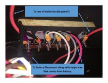
The 12v disconnect switch is outside. I pulled some coroplast off so now I see where the wires come from that are going into the disconnect, and I can see where it's going out of the disconnect (which is directly to a 100A fuse and directly into inverter from there).
Don't worry! You gave me confidence to dig into it further. I want to learn and I want to do it right. Check out my post I just did w/ some pics and a little vid.