


daklein
New Member
- Joined
- May 8, 2020
- Messages
- 190
Shucks, still happening. It worked fine with the A/C on for several hours about 11a to 1p, but then later from about 3-5p it's not working.
Today the event logs for the microinverters reveal a couple things of interest.
During the afternoon not working time period, the grid-tie micros (connected in beyond the basement panel with the A/C) show all three events, grid instability, ACFreqOOR, and ACVOOR on both L1 L2. The 'off-grid' solar micros connected in at the closer garage panel show only grid instability, ACFreqOOR.
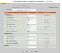
During the working pretty normal period, both show GridInst and ACFreqOOR, but no ACVOOR. I think these ACFreqOOR events are from the SMAs limiting the solar output, normal behavior with the FLA near full. The grid-tie system shows only one or two ACFreqOOR events; it's freq trip limit is set to 61.3 vs. the default 60.5 of the 'off-grid' micros. The original goal there is to keep the GT system always producing because there's an 11c/kwh REC that I get from that.
So, maybe noise or oscillation is bigger out at the GT array. More microinverters are there, and it's further away and past the A/C load. Maybe I'll try EMI filters at the microinverters, one on each 15a circuit. They could fit in the combiner box.
 photos.app.goo.gl
Today's scope video during the issue shows a couple things, I think....
photos.app.goo.gl
Today's scope video during the issue shows a couple things, I think....
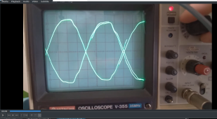
t=0-10s, L1 and L2 look pretty similar, the leads are grounded to the neutral bar, and this is the voltage at the SIs, in the AC1 distribution box. I haven't calibrated the scope voltage, but assuming it's close, it reads about +-160-170 volts, that should be about right. (see on the Ch1 knob, with L1, 5v/div * 10x probe
the frequency is bouncing, the wavelength is changing quickly, same on both legs. the X time axis is 2ms/div, x about 8 divisions per sinewave, so .016 sec period. 1/.016 is 62.5 hz. Again I haven't calibrated the X axis either, but it's about right.
How much is it bouncing? watching the video judging how much the per cycle period is, or freezing it at 9s happens to show it, it looks like about .8ms or +-.4 ms (+- 1 minor division = 2ms/5 = .4s). So, that's +-.4ms / 16ms = +-2.5% and that's 61.5 to 58.5 hz. I could set the microinverters profile further out in freq than this, up 62.5, that might help. Voltages are mostly far out, but the 'slow' limit could be more.
t=20s, lissajou plot doesn't show any phase shifting, the line is fixed slope, it's higher freqs on top of the main 60hz
t=45s, L1+L2 plot shows the voltage difference away from both L1 & L2 being perfectly opposite voltages. The X axis time scale is 2ms/div again. It looks like maybe 12 peaks within the one 60hz cycle (8 div). So whatever is going on is about 720hz? What would that be...
the vertical axis is 1v/div * 10x probe, so it looks like +-10 volts p-p of noise.
I could see what the scope looks like out at the micro combiner box, or the basement panel.
Today the event logs for the microinverters reveal a couple things of interest.
During the afternoon not working time period, the grid-tie micros (connected in beyond the basement panel with the A/C) show all three events, grid instability, ACFreqOOR, and ACVOOR on both L1 L2. The 'off-grid' solar micros connected in at the closer garage panel show only grid instability, ACFreqOOR.
During the working pretty normal period, both show GridInst and ACFreqOOR, but no ACVOOR. I think these ACFreqOOR events are from the SMAs limiting the solar output, normal behavior with the FLA near full. The grid-tie system shows only one or two ACFreqOOR events; it's freq trip limit is set to 61.3 vs. the default 60.5 of the 'off-grid' micros. The original goal there is to keep the GT system always producing because there's an 11c/kwh REC that I get from that.
So, maybe noise or oscillation is bigger out at the GT array. More microinverters are there, and it's further away and past the A/C load. Maybe I'll try EMI filters at the microinverters, one on each 15a circuit. They could fit in the combiner box.
0 new items by Dale
t=0-10s, L1 and L2 look pretty similar, the leads are grounded to the neutral bar, and this is the voltage at the SIs, in the AC1 distribution box. I haven't calibrated the scope voltage, but assuming it's close, it reads about +-160-170 volts, that should be about right. (see on the Ch1 knob, with L1, 5v/div * 10x probe
the frequency is bouncing, the wavelength is changing quickly, same on both legs. the X time axis is 2ms/div, x about 8 divisions per sinewave, so .016 sec period. 1/.016 is 62.5 hz. Again I haven't calibrated the X axis either, but it's about right.
How much is it bouncing? watching the video judging how much the per cycle period is, or freezing it at 9s happens to show it, it looks like about .8ms or +-.4 ms (+- 1 minor division = 2ms/5 = .4s). So, that's +-.4ms / 16ms = +-2.5% and that's 61.5 to 58.5 hz. I could set the microinverters profile further out in freq than this, up 62.5, that might help. Voltages are mostly far out, but the 'slow' limit could be more.
t=20s, lissajou plot doesn't show any phase shifting, the line is fixed slope, it's higher freqs on top of the main 60hz
t=45s, L1+L2 plot shows the voltage difference away from both L1 & L2 being perfectly opposite voltages. The X axis time scale is 2ms/div again. It looks like maybe 12 peaks within the one 60hz cycle (8 div). So whatever is going on is about 720hz? What would that be...
the vertical axis is 1v/div * 10x probe, so it looks like +-10 volts p-p of noise.
I could see what the scope looks like out at the micro combiner box, or the basement panel.
Attachments
Last edited:


") , or only use UL-1741-SA inverters with frequency-watts enabled.
, or only use UL-1741-SA inverters with frequency-watts enabled.