diy solar

diy solar

Some Modeling to go with Will's current sharing videos.

Yup.... I wonder about this too. In the DIY world we tend to fixate on doing crazy-ass stuff to minimize a possible problem....but in the bigger picture it may not be a big enough problem to even worry about. @Will Prowse likes to point out that for solar, the ultimate demise of the battery is likely to be calendar aging and he has a very good point. All these things we do to try to get the batteries to last longer may not make one iota of difference in the long run.
Some DC power supplies can be paralleled. Usually that means one sits in CV mode while another is in CC at times.

A "400V" battery made from 48V batteries and boost circuit could, with communications, share current and synchronize SoC.

A battery bank with BMS can't do that, not unless some SMPS is build in, e.g. a buck converter designed for CV/CC operation. It just contains cells and FETs.

If you need a significant distance between batteries and inverter, putting a busbar near inverter and running longer wires from individual batteries may help with balancing, using resistance of the wires. That could help reduce impact of differing internal resistance, at least somewhat.
My main concern is that when batteries are full/empty that the rest will see a higher current, until there is only one left. I assume there will be current protection in the BMS, depending on the BMS and not have to rely on manually having to reset breakers. But communication and some management would be nice to have especially for server rack batteries.

Anyway, following this thread with interests.
 
All these things we do to try to get the batteries to last longer may not make one iota of difference in the long run.
My primary battle is with heat, so I don't think I can talk about calendar aging yet. My installation is essentially a solar trailer that I bought from a friend who finally was able to run power lines to his farm. He had done a few things wrong, so he discounted it enough to get me interested.

The primary problem is that the trailer is not insulated, so the batteries are subjected to quite a bit of heat for a large portion of the year. I'm not going to buy new batteries until I solve the heat problem. Of course, solving the heat problem will probably need some power. I'm still scratching on the back of an envelope to figure out the best way to solve all of the problems at once.

Right now I'm leaning toward ripping everything out of the trailer, then digging a pit about four feet down and putting a small insulated shed over it and reinstalling the equipment in there. I can then sell the trailer if I want to. I really like the trailer, though, so I may try to insulate it and draw cool air from my two conduits (120' and 80') that are 20" underground. The simple button is to draw in the cool air from the conduit and pipe it through an insulated box around the batteries. The next easiest button is a micro A/C or small freezer to cool the insulated box around the batteries. The joy of solving these things is why I DIY!

I didn't mean to hijack the thread, but I just wanted to point out that we don't all get to keep our systems in a nice air conditioned space. The odds of seeing calendar aging issues goes way down with wild temperature swings.
 
for solar, the ultimate demise of the battery is likely to be calendar aging and he has a very good point. All these things we do to try to get the batteries to last longer may not make one iota of difference in the long run.
keeping the battery cell material between 10 and 25 degrees celsius

according to the research i've read, doing that will mitigate calendar aging more than allowing higher temperatures e.g. 30,40 C

almost all the research about calendar aging i've seen clearly describes a temperature dependence in this effect
  • cold climates mainly require Heating
  • moderate climates mainly require Heating and/or Circulation Cooling
  • varied climate requires Heating, Active Cooling and/or Circulation Cooling
as you say, with DIY, sometimes the fun of it can supersede the utility of a given project. it's just fun to yak shave sometimes.

I've seen lots of active heating projects on this forum, and some ventilation cooling, but I don't remember seeing any active cooling ones. Some keep their batteries in an air conditioned space, which is effective the same thing, but in this case I'm talking about a thermal regulation system specific to the battery pack that is capable of active heating and active cooling.

most won't do this, complex, difficult to engineer etc... and for good reasons. i'm taking a crack at it and look forward to do more experiments and share as progress goes :) half of the merit of effort is the fun of learning for me. but also i do believe that there is a specific temperature dependence on cell calendar aging, and believe there is an empirical case to be made for the expected utility of active thermal management ?
 
Right now I'm leaning toward ripping everything out of the trailer, then digging a pit about four feet down and putting a small insulated shed over it and reinstalling the equipment in there. I can then sell the trailer if I want to. I really like the trailer, though, so I may try to insulate it and draw cool air from my two conduits (120' and 80') that are 20" underground. The simple button is to draw in the cool air from the conduit and pipe it through an insulated box around the batteries. The next easiest button is a micro A/C or small freezer to cool the insulated box around the batteries. The joy of solving these things is why I DIY!
I have a few thoughts/cautions on earth tube work..... but that is probably best left for a different thread. If you decide to start one, let me know.
 
I think a lot of guys are underestimating the resistance added by the Mosfets in the BMS when looking at the current imbalance.
I have three eFlex batteries that use a Big Relay for switching on and off the terminal to battery contact during charging and discharging.
I have all equal length wires going to Busbars and then to the Inverter and the one EG4LL battery that I have produces half the current during charging and discharging. The eFlexs are almost in perfect sink during every cycle while the EG4 lags by a lot. This is not just at the high points of the cycling but at any given point it will be from 30% to 50% lower current Charge/Discharge from the EG4.
I cannot imagine this is due to the ESR being that different between packs. It has got to be Mosfet vs Mechanical relay resistance.
Will is using mix brands of batteries and sizes, so it makes it kind of harder to interpret what is going on.
 
Last edited:
I think a lot of guys are underestimating the resistance added by the Mosfets in the BMS when looking at the current imbalance.
I have three eFlex batteries that use a Big Relay for switching on and off the terminal to battery contact during charging and discharging.
I have all equal length wires going to Busbars and then to the Inverter and the one EG4LL battery that I have produces half the current during charging and discharging. The eFlexs are almost in perfect sink during every cycle while the EG4 lags by a lot. This is not just at the high points of the cycling but at any given point it will be from 30% to 50% lower current output/Input from the EG4.
I cannot imagine this is due to the ESR being that different between packs. It has got to be Mosfet vs Mechanical relay resistance.
Will is using mix brands of batteries and sizes, so it makes it kind of harder to see whats going on.
some addition info about that available here, for a specific BMS that is different than the one being tested in the video. mainly hoping to add some concrete reference numbers to get the quantitative ball rolling, so to speak :)


Go by Rds_ON.

Five back to back pair on top, five back to back pair on bottom side. 3.2 milliohms x 2 for each back to back = 6.4 milliohms @ 25C.

Ten back to back pairs in parallel = 0.64 milliohm series resistance at 25C.

Heating watts @ 200A = 200^2 x 0.64 milliohms = 25.6 watts. Won't take 200 amps very long before thermal shutdown.
For continuous current rating, no more than 10 watts heating with the limited heat sinking provided, = sqrt (10w / 0.64 millohms) = 125 amps.

Since Rds_ON goes up as MOSFET's get hot, 100 amp max continuous is more realistic. 50% derating, about par for Chinese BMS's.

on the order of 0.64 Ohms or nearly one ohm, in that example. absolutely makes sense that variance between BMS units would result in a difference in charge/discharge current as a result of the MOSFET resistances. e.g. one BMS is 0.60 ohm and another BMS is 0.70 ohm, etc..
 
For the JBD BMS, here is information about the MOSFET and Resistance thereof, from Steve himself!


each individual MOSFET is rated for about 1.3 milliOhm, and there are apparently in 15 parallel, two series

so each "lane" should be (1.3*2) or 2.6 milliOhm and 15 of those "lanes" in parallel for the JBD BMS rated for 100/120A continuous

mosfet datasheet : https://datasheet.lcsc.com/szlcsc/HY4903B6_C133393.pdf

each one is rated for 1116 A pulsed drain current, limited by temperature, and 314 A continuous drain current (at 25C). of course it will overheat quickly with most flat heat spreaders. but it's good to know. 15 of those in parallel sounds like a pretty great tradeoff for the vulnerability of MOSFET in general!
 
working this out on my own propellorhead pace :D

@robby made me more curious about How Much Variance of Resistance From BMS to BMS.

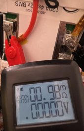
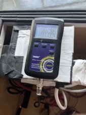
i attached tr1035+ meter to two JBD BMS here. ensured that the mosfet are closed (on) while the measurement was taken. its from C- to P- terminals

1644538101748.jpeg1644538113470.jpeg

0.98 milliOhm and 0.48 milliOhm were the results for two 4S JBD 120A BMS. i could have a systematic or methodological error, or maybe they are really just different. hope this helps.

JBD BMS #1JBD BMS #2
0.00098 Ohm0.00048 Ohm
0.98 milliOhm0.48 milliOhm
 
this makes me realize that if i wanted to eliminate this effect entirely, buying extra BMS and selling the ones that are very extreme relative to average resistance, would be one way. tedious. inter-pack active balancing perhaps achieve similar.

reminds me of how some cell vendors will match/batch the product based on internal resistance.

how funny would it be if, when buying multiple BMS, they were also matched to be similar internal resistance?

value? just musing :) thanks everyone!
 
working this out on my own propellorhead pace :D

@robby made me more curious about How Much Variance of Resistance From BMS to BMS.

i attached tr1035+ meter to two JBD BMS here. ensured that the mosfet are closed (on) while the measurement was taken. its from C- to P- terminals

View attachment 83265View attachment 83266

0.98 milliOhm and 0.48 milliOhm were the results for two 4S JBD 120A BMS. i could have a systematic or methodological error, or maybe they are really just different. hope this helps.

JBD BMS #1JBD BMS #2
0.00098 Ohm0.00048 Ohm
0.98 milliOhm0.48 milliOhm
That is a pretty big difference!!!!

However, when dealing with such small resistance, I wonder how accurate you can be. Just a fleck of dirt under the alligator clip could make that much difference.
 
That is a pretty big difference!!!!

However, when dealing with such small resistance, I wonder how accurate you can be. Just a fleck of dirt under the alligator clip could make that much difference.
will redo it with ring terminals later ;)

big agree alligator clips are prone to high contact resistance (low contact patch area)!
 
That is a pretty big difference!!!!

However, when dealing with such small resistance, I wonder how accurate you can be. Just a fleck of dirt under the alligator clip could make that much difference.
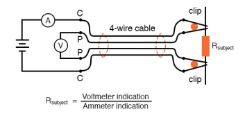
Here is a post with more information about how four wire resistance meters operate. It's kind of cool!

The alligator clips on this tr1035+ device, "Kelvin clips" as it were, each of them, is actually Two electrical connections. This way, current is run through one, and voltage measured through the other. It is less prone to error than two wire resistance meter, in my opinion, but a small contact patch (fleck of dirt) with high resistance of course still error resulting. cheers!
In regular, “alligator” style clips, both halves of the jaw are electrically common to each other, usually joined at the hinge point.
In Kelvin clips, the jaw halves are insulated from each other at the hinge point, only contacting at the tips where they clasp the wire or terminal of the subject being measured. Thus, current through the “C” (“current”) jaw halves does not go through the “P” (“potential,” or voltage) jaw halves, and will not create any error-inducing voltage drop along their length:
1644540596932.png
 
Here is a post with more information about how four wire resistance meters operate. It's kind of cool!

The alligator clips on this tr1035+ device, "Kelvin clips" as it were, each of them, is actually Two electrical connections. This way, current is run through one, and voltage measured through the other. It is less prone to error than two wire resistance meter, in my opinion, but a small contact patch (fleck of dirt) with high resistance of course still error resulting. cheers!


View attachment 83267
It is essentially what I like to do: Load the system up with a good size current and then measure the voltage and current. For a small resistance that will always be a lot more accurate than a two-wire ohm meter.... even a fluke.
 
Warning: I go full propeller head on this post!!! ?

@Will Prowse just released a couple of videos about hooking parallel batteries together. One commenter claimed 4 batteries in parallel but hooked up 'Diaganaly' would stay balanced. 2 batteries in parallel with diagonal connections is balanced any more in parallel will be out of balance.

I decided to nerd out and try to model the diagonal battery hook-up. (I tried this once before but got wrapped around the axil... I tried a different approach this time and it worked out)

For simplicity, I only modeled 2 in parallel with diagonal connections and 3 in parallel with diagonal connections.

2 Batteries:

View attachment 83062

Assume the resistance of the interconnecting cables are all identical and of value R.
Since each battery is only carrying half the current, the cables between the two positive terminals will carry half the total current. Likewise, the current between the two negative terminals will carry 1/2 the current.

To calculate the voltage on battery A, start at the battery A negative terminal and add the voltages as you go around the loop.
Va = The voltage across R2 + Voltage across the load. The voltage across R2 = 1/2 I * R, so the voltage across battery A is VL + 1/2*I*R

Now calculate the voltage on battery B by starting at the Battery B negative terminal and adding the voltages around the loop..... it comes out to 1/2*i*R + V2
So.... the voltages on the two batteries are the same and therefore the load is the same and they are balanced.

Now let's look at 3 batteries.

View attachment 83061

The big difference here is that the current on each of the interconnects is not the same

The positive linkage between Battery C and Battery B is 1/3 of the total current
The positive linkage between Battery B and Battery A is 2/3 of the total current.
Similarly, the interconnects on the negative are 1/3 and 2/3 of the total.
(This turns out to be a good first approximation. It is good enough to prove the point but not 100% accurate... more on this below)

Now when you go around the loop and calculate the voltages you get this:

Va = Vl + i*R
Vb = Vl + 1 1/3*I*R
Vc = Vl + I*R

As you can see, the voltage on battery B is slightly higher than on batteries A and C. This means it will be contributing less current. This is not a balanced arrangement. As you add more batteries, this pattern continues to get worse. The middle batteries will always be stressed less than the outer batteries.

Notice that since the voltages are not the same across all 3 batteries, the current contribution of B will be less than for A and C. This is why I said the 1/3 - 2/3 current model is only a first approximation. However, after doing a sensitivity analysis on the approximation, I concluded that it does not change the model in any significant way.
Yeah Baby that's how you Do it.
 
Back
Top