diy solar

diy solar

Some pictures from my boat upgrade

svsagres

Solar Enthusiast
Joined
Nov 14, 2021
Messages
300
Thought I'd share some pictures of the upgrade I did on my 27' sailboat

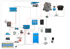
First, the main DC electrical compartment. On the top-right side of the image is a 460Ah 2p4s LiFePO4 battery, managed by a REC ABMS. The Blue Sea 7713, and Lynx Distributor are on the high side. The low side of the DC system (just below the photo) is controlled via Victron Smart BatteryProtect. The Victron SmartShunt is used as an Energy Meter for the DC loads on the boat. The Black battery switch is a DC Disconnect for our MultiPlus II inverter/charger. From top to bottom, the feeds into the Lynx Distributor are Alternator, Inverter/Charger, Solar, and Battery Feed.

IMG_2327.jpeg

Next is the Victron Multiplus II 12/2000/80-50 inverter/charger. The picture was taken before we had finalized the wiring and closed up the lid.

IMG_2297.jpeg

Lastly, for this part of the boat, the overview. All this equipment is located in the voids under the quarterberth.

IMG_2300.jpeg

On the engine itself, we have our new (to us) 85A Hitachi Alternator, controlled by a Wakespeed WS500 advanced regulator. The engine is a Yanmar 1GM10 single cylinder, 10HP (well, 10HP 40 years ago) diesel. However, when we derate the alternator to 35A, it can produce that 35A continuously, and the alternator only heads up to 52C. We can flip a toggle switch, and kick the alternator to 80A, but at that point we start smelling belt. We may derate to 65A or so, to see if that makes a difference.

IMG_2332.jpeg

In the Lazarette, we have both the Starter battery (a Group 24 Marine Start battery) which is maintained by a Victron Orion Tr 18A DC to DC charger. We also have mounted in there the Wakespeed Regulator. It communicates with both the Victron Cerbo GX and the REC ABMS to properly manage the battery. It's an incredibly slick system. There's also the shunt for a BMV-712 that is being used to monitor the start battery.

IMG_2333.jpeg

Overall, the system so far has been extremely nice to work with. The remote monitoring provided by the Cerbo GX has been second to none. I'm very happy with the system, and it worked flawlessly over the first week we actually took it out on the water.
 
Very nice setup. How much solar are you running with that configuration? Love to see a wiring diagram if you have anything like that. I've been trying to speculate a fairly basic setup for a 25' Catalina sailboat mostly used for cruising the lake and some overnight/weekend type trips.
 
Very nice setup. How much solar are you running with that configuration? Love to see a wiring diagram if you have anything like that. I've been trying to speculate a fairly basic setup for a 25' Catalina sailboat mostly used for cruising the lake and some overnight/weekend type trips.
We have 120W of solar on the dodger (2x 60W 24V solar panels). We could probably add more capacity if we didn't mind turning the boat into a floating PV power station, but I'll admit to some vanity in how she looks on the water. The rest of deck space is taken up by control lines and halyards (everything runs from the mast to the cockpit for single handing) and we don't have an arch/davits behind the cockpit, and don't want them.

I've attached a rough schematic of the system. There were a few changes made as we were actually building it, but it's more or less correct.

Our reference trip, though, is for about 6 to 10 days away from the dock, or at least away from a dock with power. Putt-putting and sailing around. Our loads are fairly high for a small boat, as we have refrigeration on the icebox, pressurized water (including potentially hot water off of the inverter), and more electronics than you can shake a stick at. Base load, with the icebox off, is around 20W to run our AIS, instruments, power system electronics, maintain the starter battery, and power the LTE router.
 

Attachments

  • Electrical Schematic.png
    Electrical Schematic.png
    323.9 KB · Views: 95
Thank you for that! I'm still new to all this and it's kinda over my head, but that's a great setup! How does the 120W solar do with your fairly large battery bank? Is that more or less able to keep you topped off?
 
Thank you for that! I'm still new to all this and it's kinda over my head, but that's a great setup! How does the 120W solar do with your fairly large battery bank? Is that more or less able to keep you topped off?
If we’re not aboard, and the boat is in what amounts to standby mode, it is enough to keep the battery stable. If we’re actually out and about/using the boat, it is realistically a range extender; the difference between basically giving us an extra 25% boost or so. So, worth having, but we can’t run off of them indefinitely. That’s just the nature of being on a small boat that we don’t want to turn into a floating power station.
 
@svagres Thank you for this thread and the good documentation and diagram. I am trying to understand...
The Lynx Distributor seems to be at the center of your system, and is something we should consider because it simplifies the wiring mess .
The CerboGX appears to be connected to Wakespeed WS500, MPPT 75/115 Smartsolar, and the Smartshunt, via what, canbus? Do you use your cell phone and bluetooth to view and control the wakespeed, smartsolar, bms, etc.?
I don't see the canbus connection from Wakespeed WS500 to the REC BMS. Is there one?
What is the dark box above the batteries that is connnected to the BMS?
The Smartshunt looks like it is between the Lynx and a panel. What is the panel? House Panel or your Always on Panel?
The Smart Battery Protect appears be between this Panel and the Batteries, does it just disconnect at some low voltage?
The Rec BMS appears to be communicating with the black box above the batteries, the Blue Sea 7713 switch and a positive bus, but you advise that the Wakespeed WS500 also communicates with the BMS. Is this correct?
Are you on a mooring most often, or at a slip? We are most often on a mooring, so I am considering eliminating the Victron Multiplus II 12/2000/80-50 inverter/charger, but recognize that I would be losing some good capabilities to charge at a slip and to invert for 120vac. The problem I have is there is not a good locker or place to hang this device.
Also are you showing an Isolation transformer at the shore connection?

Thank you for posting this!

PS: It might help if you could update the diagram and label things. I couldn't zoom in far enough to see all the devices. IE what are shunts and what are just post/busbar?
 
Last edited:
I also have a larger question for you. How sensitive do you think this system is compared to FLA or Firefly Carbon batteries? I am thinking about sailing offshore where things happen... This is coming from an article John Harries wrote in "Attainable Cruising" Building a Seamanlike Lithium Battery System July 3, 2022 "Lithium batteries have many benefits, but are too complicated and fragile, and not fault tolerant enough, to be relied upon exclusively on an offshore boat. Here’s how to fix that...."

Answer: Have a simple and easy to use FLA backup system, which protects against BMS and other failures. His suggestion is have a lead acid bank providing all critical loads (navigation, nav lights, etc), which is charged by the LFP bank. The charge bus (alternator, solar, inverter/charger) can be switched to either bank (would require reprogramming however). Non-critical loads would be supplied by LFP.

How "sensitive" and "reliable" do you think your LFP system is? What will you do when the BMS fails or one of the other components disconnects the LFP? How will you limp home.?
 
Last edited:
@svagres Thank you for this thread and the good documentation and diagram. I am trying to understand...
The Lynx Distributor seems to be at the center of your system, and is something we should consider because it simplifies the wiring mess .
The Lynx is the centre of the high-side portion of the system. It connects my solar, alternator, inverter/charger and battery. I do make use of the negative bus as the centre, but the actual centre of the positive side is a separate 600A bus bar. It has a feed to both the Lynx (via the BlueSea 7713 and a disconnect) and to the Safetyhub 150 via a Victron BatteryProtect.
The CerboGX appears to be connected to Wakespeed WS500, MPPT 75/115 Smartsolar, and the Smartshunt, via what, canbus?

So the CerboGX connects to the Wakespeed WS500 and the REC BMS via CAN BUS. The actual cabling runs BMS->WS500->CerboGX which then connects into the rest of my NMEA2000 network. The SmartSolar connects via VE.Direct, as does the Smart Shunt (and the BMV). Note that neither the BMV nor the SmartShunt are critical. The SmartShunt is just being used as a DC Energy meter to monitor the DC side of my power system, and the BMV is a bit silly as it's just monitoring my starter battery. I'm an instrumentation geek, so I like to monitor all the things.

Do you use your cell phone and bluetooth to view and control the wakespeed, smartsolar, bms, etc.?

Not shown in the diagram is Victron GX Touch50 touchscreen. I also have an LTE router aboard that connects the Cerbo to the internet, so I can monitor the whole thing remotely through Victron's VRM portal.

I don't see the canbus connection from Wakespeed WS500 to the REC BMS. Is there one?
Yes, ther eis one. It's a little hard to see in the diagram, but it heads left from the REC (the black box with all the connections to the battery) up around the top and into the WS500. I deliberately wired it REC->WS500->Cerbo so that the REC and WS500 were directly connected, to remove a potential point of failure.
What is the dark box above the batteries that is connnected to the BMS?
Yes.
The Smartshunt looks like it is between the Lynx and a panel. What is the panel? House Panel or your Always on Panel?
Main house fuse panel. The positive to that panel goes through the Smart Battery Protect (which is also controlled by the BMS)
The Smart Battery Protect appears be between this Panel and the Batteries, does it just disconnect at some low voltage?
It's controlled by the BMS, I didn't get that control line into the diagram, sorry. (Like I said, this is a rough diagram)
The Rec BMS appears to be communicating with the black box above the batteries, the Blue Sea 7713 switch and a positive bus, but you advise that the Wakespeed WS500 also communicates with the BMS. Is this correct?

Yes, the black box in that diagram is actually the pre-charge circuit. It puts a 21Ohm resistor across the 7713 for several seconds prior to closing the relay so that the capacitors in the inverter/charger can charge up more slowly. The unlabeled black box directly above the battery is the BMS.
Are you on a mooring most often, or at a slip? We are most often on a mooring, so I am considering eliminating the Victron Multiplus II 12/2000/80-50 inverter/charger, but recognize that I would be losing some good capabilities to charge at a slip and to invert for 120vac. The problem I have is there is not a good locker or place to hang this device.

I'm normally at a dock, plugged into shore power. However, 120W of solar is enough to keep my batteries at the idle charge level I want (I let it back off to 13.2v). Through VRM, remotely, the day before I head out I log in, remove the voltage limit (and let the BMS be in full control again), and turn the inverter/charger on. It then runs the batteries back up full, and also reheats my hot water tank. The Inverter/charger itself is in an otherwise unused void under our quarterberth that's just big enough for the unit, but also vents all the way into the transom.

Also are you showing an Isolation transformer at the shore connection?

I have a galvanic isolator, as I didn't have room in my laz for an isolation transformer. It's good enough for my needs.

Thank you for posting this!

PS: It might help if you could update the diagram and label things. I couldn't zoom in far enough to see all the devices. IE what are shunts and what are just post/busbar?
One of these days, I'll try. :) Right now, I'm too busy actually out using it, sorry.
 
I also have a larger question for you. How sensitive do you think this system is compared to FLA or Firefly Carbon batteries? I am thinking about sailing offshore where things happen... This is coming from an article John Harries wrote in "Attainable Cruising" Building a Seamanlike Lithium Battery System July 3, 2022 "Lithium batteries have many benefits, but are too complicated and fragile, and not fault tolerant enough, to be relied upon exclusively on an offshore boat. Here’s how to fix that...."

Answer: Have a simple and easy to use FLA backup system, which protects against BMS and other failures. His suggestion is have a lead acid bank providing all critical loads (navigation, nav lights, etc), which is charged by the LFP bank. The charge bus (alternator, solar, inverter/charger) can be switched to either bank (would require reprogramming however). Non-critical loads would be supplied by LFP.

How "sensitive" and "reliable" do you think your LFP system is? What will you do when the BMS fails or one of the other components disconnects the LFP? How will you limp home.?
I absolutely trust the system right now. It's been rock solid, and in the 2 month that it's been operational, I haven't had a single disconnect. All my charge controls are contolled by the BMS, so it will slow things down while the balancer works, and/or it reaches towards the top.

If I get a BMS failure, I can force the system on and limp home (the Wakespeed will go to 13.2v if it doesn't hear from the BMS), but additionally my engine start battery is a basic marine start FLA. The engine itself is basically clockwork (Yanmar 1GM10) so I can go a long time without recharging the start battery.
 
@svagres That is reassuring. We know that BMS can get flukey and connections fail. You could put your essential Navigation system and Nav lights on the FLA battery to make any LFP shutdown less intrusive, alternatively, you could possibly use a 3-way switch for the entire panel and just manage the loads yourself in that emergency event.
John Harries wanted essential equipment on a separate FLA emergency battery other than the starter due to starter spikes etc and safety. However for small boats like ours that is totally impractical and you are doing what is necessary at that point anyway.

Doesn't the wiring get more complex if you need to be able to shut down the LFP system (as if in failure) and continue using the FLA Starter Battery? The alternator sensing leads have to change from one battery to another, and the Panel loads need to be moved to the FLA. The starter is already on the FLA. How would your system change with these requirements? What adjustments would you need to make? I am guessing that the battery and alternator monitoring will not be working, which is probably ok as long as the system works on FLA.

I just read that the SmartBatteryProtect does not work well with Inverters, and I thought of your system, but I now see that the inverter does not use the SmartBatteryProtect at all, or perhaps it uses that REC Precharge Delay that I see in the pictures. That black device just above the batteries must be the REC BMS

Very sorry about all the questions, but I am trying to figure this out so it works properly for my use, and you've probably already considered all these situations.
 
Last edited:
Thanks for the post. Very inspiring install. To deal with a possible LFP failure, I've got an A-Off-B switch which allows me to switch out the LFP bank for an FLA bank. I left the original A-B-Both-Off switch in place so have two FLA banks to choose from.
 
@svagres That is reassuring. We know that BMS can get flukey and connections fail. You could put your essential Navigation system and Nav lights on the FLA battery to make any LFP shutdown less intrusive, alternatively, you could possibly use a 3-way switch for the entire panel and just manage the loads yourself in that emergency event.
John Harries wanted essential equipment on a separate FLA emergency battery other than the starter due to starter spikes etc and safety. However for small boats like ours that is totally impractical and you are doing what is necessary at that point anyway.

So the probability of the cells themselves going bad is pretty low in my estimation. The most likely problem is going to be with the BMS itself. If the BMS fails, I can force both the 7713 and the BatteryProtect on manually and limp home. The FLA for the starter is more to avoid welding my solenoid.

Doesn't the wiring get more complex if you need to be able to shut down the LFP system (as if in failure) and continue using the FLA Starter Battery? The alternator sensing leads have to change from one battery to another, and the Panel loads need to be moved to the FLA. The starter is already on the FLA. How would your system change with these requirements? What adjustments would you need to make? I am guessing that the battery and alternator monitoring will not be working, which is probably ok as long as the system works on FLA.

I just read that the SmartBatteryProtect does not work well with Inverters, and I thought of your system, but I now see that the inverter does not use the SmartBatteryProtect at all, or perhaps it uses that REC Precharge Delay that I see in the pictures. That black device just above the batteries must be the REC BMS

Yeah, the high side (inverter, alternator, and solar) is controlled by a blusea 7713 contactor. I had to do a little bit of circuity (a pmos FET and biasing resistor) to get the signalling right between the precharge box and the 7713, but it’s reliable. If things go bad, I can always manually force the 7713 on with the knob.
https://www.currentconnected.com/product/rec-4sabms/
Very sorry about all the questions, but I am trying to figure this out so it works properly for my use, and you've probably already considered all these situations.
No worries. :)
 
bluesea 7713 contactor. I had to do a little bit of circuity (a pmos FET and biasing resistor) to get the signalling right between the precharge box and the 7713, but it’s reliable
As an Architect (generalist) this is a little intimidating, maybe circuit diagram would help. What is "bias"? Is that reversing the current +/- or something? I guess you picked the magnetic latching Bluesea 7713 ML-RBS Battery Switch because it also allows manual and remote? Listed at $291 There are some other less expensive magnetic latching relays with low draw but they don't have manual and remote.
500 Amp magnetic latching switch provides high amperage switching under load, manually or from remote locations
  • Manual override knob provides an added level of safety allowing control with or without power and offering LOCKED OFF capability for servicing
  • LED output to remotely indicate switch state - requires optional LED


I found this offgridsoftwaresolutions thread about Connecting REC BMS, WS500 & CerboGX very interesting
 
Thanks for the post. Very inspiring install. To deal with a possible LFP failure, I've got an A-Off-B switch which allows me to switch out the LFP bank for an FLA bank. I left the original A-B-Both-Off switch in place so have two FLA banks to choose from.
How do you wire the alternator sense+ and sense- ? -- To the LFP batteries would be the most accurate way, but then in a LFP failure situation, those sensors need to be on the starter battery, but how? Would the A-Off-B switch have separate contactors for the Alternator sense+ wire? I was also considering a Smart DC-DC charger from the LFP to the FLA starter, I don't know what would happen to the DC-DC device, if you start charging up the FLA starter battery. I am trying to picture what happens to the panel loads here too, would they switch over to FLA?
 
How do you wire the alternator sense+ and sense- ? -- To the LFP batteries would be the most accurate way, but then in a LFP failure situation, those sensors need to be on the starter battery, but how? Would the A-Off-B switch have separate contactors for the Alternator sense+ wire? I was also considering a Smart DC-DC charger from the LFP to the FLA starter, I don't know what would happen to the DC-DC device, if you start charging up the FLA starter battery. I am trying to picture what happens to the panel loads here too, would they switch over to FLA?
So what you need to differentiate is whether you have an actual LFP failure or a BMS failure. The former isn’t very common, LFP cells are just electrochemistry, same as Lead Acid. BMS failures are going to be more common. If you’re using a Daly BMS, or some other FET based BMS, then if the BMS fails you’re pooched.

The REC I’m using is contactor based. If it fails, I can override it and manually close the main contactor, allowing me to charge it. Because it’s no longer getting the messages from the BMS, the Wakespeed will go into “limp mode” and set its voltage limit to 13.2v, which is safe for the LFP battery. That’s around 60% charge, and more than good enough to get back to the dock.
 
Good explanation. Does the PRE-Charge delay opening of the latching relays by closing the black wires to the relay at some adjustable time delay from the BMS no/nc signal?
 
Good explanation. Does the PRE-Charge delay opening of the latching relays by closing the black wires to the relay at some adjustable time delay from the BMS no/nc signal?
So the precharge box is only on the high side (since the large capacitors in the inverter and solar are there). It gets the signal from the BMS (BMS takes it to +vbatt) it then connects a 20ohm power resistor across the contactor. Some seconds later, the precharge box connects its contactor output to ground. (An open collector output).

The problem is that the 7713 needs a +12v on its control input to close the contactor. To remedy this, I made a little circuit with a p-type FET and a 120k resistor, and potted it in adhesive shrink tube.

Thus, when you flip the little switch that controls the BMS, you initially hear the click of the relay in the BMS and the precharge, then a few seconds later the louder ker-klunk of the 7713 closing.

All that said, though, it’s something that you’re rarely off ever going to hear. We leave our power system on at all times, to keep the bilge pumps powered just in case, and the monitoring electronics alive. The only time that gets shut off is if we’re doing electrical work.
 
I think I see, I would like to know how to do that potted wiring for the 7713.

So the Pre-charge does not delay the signal for the Wakespeed WS500 to drop the field current? Is that just done with a Canbus signaling to the Regulator, before the latching relay is operated?
 
I think I see, I would like to know how to do that potted wiring for the 7713.

So the Pre-charge does not delay the signal for the Wakespeed WS500 to drop the field current? Is that just done with a Canbus signaling to the Regulator, before the latching relay is operated?
In my setup, it’s extremely unlikely for the BMS to ever open the 7713 on its own without warning. The BMS is managing all the the charging over CAN. If a call starts going high, it will order the current limit down to something like 2A to let the active ballancer do its thing. We’ve been running the system for 3 months, using the full battery capacity, and the system has never operated the relays except when we’ve deliberately exercised it. The BMS is in full control of the charging system, if the rest of the charging system loses contact with the BMS, it goes into a safe mode.

If the WS500 stops receiving CAN messages, it will drop into “limp” mode, setting its voltage limit to 13.2v, which is pretty safe.

I’ll try to knock together a little diagram of the FET circuit tonight.
 
Thanks svsagres that would be very helpful. Rather than mess up your thread, I decided to pose a slightly different schematic (very rough), but much of it would be similar to your refined setup. Your thoughts would be appreciated.

Monitoring and Control Questions:
I am starting to realize that some of the Victron equipment adds up in cost and the monitoring part is quite large. It looks like the REC BMS has is own PC monitoring software which uses a certain cable and Wakespeed has a bluetooth app. I expect this software simply shows battery SOC and cells with no history or indication of charging sources etc and the Wakespeed app sets up the parameters.

Using available device software I think you would need Victron Connect on your phone or PC, using Bluetooth for Solar and DC-DC Charger. The Wakespeed bluetooth app is separate and so is the Rec software. Perhaps a couple of smartshunts using Victron Connect with bluetooth would complete the monitering. If this system can be used effectively, it would be less expensive, but I kind wonder about having so many separate apps.

Using Victron there is also an inexpensive Raspberry_pi alternative which requires: a compatible touch screen, Victron Energy VE.Direct to USB Interface ($25) using Victron OS (opensource software) to connect the Victron SmartShunt 500A ($125) and other Victron devices with VE.Direct. This would eliminate need to purchase of Victron Cerbo GX ($340) and GXtouch 50 ($200) Screen (GX product range). I'd like to monitor the energy flow between:
  1. Wakespeed WS500 - how can the Canbus information be accessed?
  2. REC BMS LFP Battery - how can the Canbus information be accessed? Add a Smartshunt too?
  3. (2) SmartSolar 75/15 - Bluetooth app and via VE.Direct port
  4. Orion TR Smart DC-DC 12/12 30 - Bluetooth app only, Victron Connect does no show current in or out.
  5. SFA Battery (perhaps) - add a Smartshunt?
The difference is that there would be $29 VE.Direct to USB cables running all over, rather than using Bluetooth or Wifi.
 
Last edited:
Back
Top