OK, so it is a maximum of 5kW or 41.7A of inverter output per leg, but is it able to pass through as much as 63A or 7.5kW per leg of grid power?
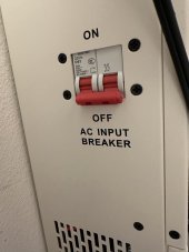
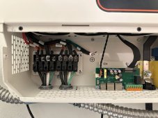
I have never tested such a large load on this machine, even though it is designed to handle pass-through loads. I understand that the manufacturer labeled it as 63A because they installed a 63Amp input breaker. However, upon closer inspection, I noticed that the wire for the AC input and output is of a smaller gauge than 6 AWG. You can see from the pictures that the incoming wire in the AFC is 6 AWG, but the wire on the terminal block is only 8 or smaller. Based on my assessment, I would not recommend using it for a long period of time with a 63Amp pass-through load, as it would likely cause the wire to overheat.
Meaning grid-consumption cannot be less than 50W or that that 50W is wasted / lost when running in battery priority while grid is present?
I’m considering to use an external transfer switch to disconnect the grid from the inverter AC input overnight to avoid any sprigs export when the sun is not shining.
I’m hoping your observation means battery consumption increases by ~50W when grid is disconnected (so it’s just a 50W minimum grid consumption level when grid is present).
I am unsure whether the power drawn from the grid, approximately 45-50W, is being wasted or used for the inverter output. At times, I manually switch off the AC input breaker to completely eliminate grid consumption, resulting in 0W usage. In an interesting test, I utilized Home Automation (HA) to send a changeover Modbus command to switch the inverter to grid power while keeping the AC input breaker in the off position. However, the inverter did not change to grid power as expected. In HA, I have set up an automation that triggers this switch based on the State of Charge (SoC) of my Battery Management System (BMS). When the SoC falls below 15%, the Modbus command is sent to the inverter to switch over to grid power.
Nevertheless, if I turn off the AC input to avoid utilizing the 50W grid power, I will lose power entirely once the battery is fully drained. As for the actual utilization of the 40-50W grid consumption by the inverter, I have yet to investigate this matter. I plan to delve into it further tonight.
OK, so 5W minimum grid consumption during daylight hours when grid is present and 50W minimum grid consumption at night…
Yes.
Fantastic. If only there were a way to force it to disconnect from grid through Modbus commands…
To eliminate grid consumption and forfeit the grid backup, I can only manually switch off the AC input.
What output levels generally cause the fans to turn on? Are they loud?
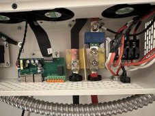
There are four fans connected in a way that they all run simultaneously and at the same speed. Two fans are dedicated to the inverter compartment, while the other two are for the Solar Charger compartment. Each compartment is equipped with a temperature sensor. If either of these two sensors detects a temperature higher than 45 degrees Celsius, all four fans will start running at low speed. Once the temperature decreases to 41.8 degrees Celsius, all fans will switch off.
If the temperature exceeds 50 degrees Celsius, the fans will continue running at a higher speed. However, it is unclear whether these fans have two or three speed settings. Generally, when the inverter output or the PV (photovoltaic) system operates at high power levels, the fans can be quite loud.
Are you generally happy with the build quality?
This is a typical Chinese-made item with a corresponding quality level. It follows the principle of "you get what you pay for." To ensure a longer lifespan for the unit, it is advisable to operate it at around 80% of its maximum capacity. Based on the wire size and overall construction, it seems that the unit is somewhat undersized for its claimed capabilities. The wiring compartment and the wiring block are both quite small, which hampers airflow and may lead to increased heat. Additionally, the unit causes frequent LED light flickering. However, apart from these issues, it performs well overall. It can effectively charge my Tesla Model 3 at 240V with a 32Amp current, provided that I do not use high-power appliances simultaneously while charging at the maximum 32Amp rate.
Do you believe the claimed efficiency numbers are roughly accurate?
The efficiency claim of the product aligns closely with the manufacturer's specifications. Through my recordings, I have observed an efficiency range of 89% to 92% when converting power from the battery to AC output. However, I am unsure about the best method to test the efficiency of the MPPT