diy solar

diy solar

Swapped out suitcase panel, copied wiring = solar overvoltage error?

Jayne

New Member
Joined
Mar 2, 2021
Messages
14
Hi there! I have a very simple Renogy 200w (2-panel/100w ea) Eclipse suitcase set-up that I pull out to charge the house batteries in my van as needed.

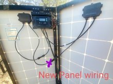
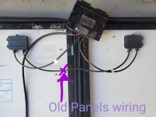
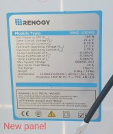
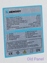
One of the100w panels got smashed, so I ordered a new 100w Eclipse panel and figured I'd just document how everything was wired and swap it out. Easy-peasy!

Except now that I have the new one attached and everything wired, I'm getting a P02 "solar overvoltage" warning. I can't figure out what I might have done wrong and I haven't found much info on solar overvoltage errors online.

I'm attaching pics of the old panel info, new panel info, old set-up's wiring and the wiring with the new panel.

Please help! I have pretty much no idea what I'm doing. I assume I did something simple incorrectly? Thank you.
 

Attachments

  • 20210302_174154.jpg
    20210302_174154.jpg
    69.4 KB · Views: 32
  • 20210302_174037.jpg
    20210302_174037.jpg
    61 KB · Views: 60
  • 20210302_173704.jpg
    20210302_173704.jpg
    96.6 KB · Views: 28
  • 20210302_173923.jpg
    20210302_173923.jpg
    122.5 KB · Views: 30
PS: the new panel came with MC4 connectors, while the old one was all directly wired. To make it work, I cut the old wires and installed MC4 ends on them, as that seemed like a better plan than trying to splice the wires together.
 
Thanks for the welcome!

It's one old panel and one new panel, which I tried to wire up exactly the same as the first two panels.

I just looked at an explainer on parallel vs. series and I do have them wired in series, but that's because the first two panels were wired in series and I copied the wiring scheme. I never had a problem with the original two.

Do you know if there's a reason series might have worked ok with my original two panels, but not with one old panel and one new one?

This is the product that I originally purchased:

 
It's a long shot but try disconnecting the panels from the charger and the battery. Leaving the panels still disconnected, connect only the battery to the charger. Then connect the panels.
 
I think your old panel specifications are not quite what they say on the label. It appears the spec they show on the label are for both of the series combined panels, they may be 6v nominal panels. Disconnect all your wiring, put them in the sun and check voltage with your meter. I'm guessing you will see 10.6ish volts on the old one and 21.2 on the new one...........please let us know the results.
Once you get it working it is far better if the controller is electrically closer to the battery-not mounted on the panels....
 
Another thing to support my hypothesis....
Take off the box cover on the old panel and post a photo of the wiring........thanks........
 
I think your old panel specifications are not quite what they say on the label. It appears the spec they show on the label are for both of the series combined panels, they may be 6v nominal panels. Disconnect all your wiring, put them in the sun and check voltage with your meter. I'm guessing you will see 10.6ish volts on the old one and 21.2 on the new one...........please let us know the results.
Once you get it working it is far better if the controller is electrically closer to the battery-not mounted on the panels....
+1
What is the spec of the SCC max PV input Voltage?

Based on the stciker of the old dual-panel,
Each panel should have
Voc of 10.60V (21.20 Voc divided by 2).
Vmp of 8.85V (17.70V divided by 2).
Imp of 11.30A.

Youe new 100W panel has
Voc of 21.20V.
Vmp of 17.7V.
Imp of 5.70A.

So when you connect one of the old panel in series with the new panel.
The system parameters are:
Voc of 10.60V + 21.20V = 31.80V
Vmp of 8.85V + 17.70V = 26.55V
Imp for series connected panels will be equal to the lowest Imp rating of the panel = 5.70A
So the system panel power will be = 26.55V * 5.70A = 151W.
 
I think your old panel specifications are not quite what they say on the label. It appears the spec they show on the label are for both of the series combined panels, they may be 6v nominal panels. Disconnect all your wiring, put them in the sun and check voltage with your meter. I'm guessing you will see 10.6ish volts on the old one and 21.2 on the new one...........please let us know the results.
Once you get it working it is far better if the controller is electrically closer to the battery-not mounted on the panels....
That makes sense.

I am in the middle of nowhere atm and don't have a multimeter with me, but I will update when I can check it.

If this is the case, will wiring in parallel fix it? Or is there another fix?

Thank you!
 
The panel specifications are correct, with a OC voltage of 21v. You have wired is series thus giving an over voltage fault indication, The PWM charge controller you have is specified for a maximum input voltage of 26 volts.


Reconnect the panels in parallel. Make sure you have a voltmeter of some type to ensure you get the polarity correct. Connect the battery first to the controller, then the panels.

Mike

Sorry 'resident asshat' typing as you posted.

 
Thanks for the welcome!

It's one old panel and one new panel, which I tried to wire up exactly the same as the first two panels.

I just looked at an explainer on parallel vs. series and I do have them wired in series, but that's because the first two panels were wired in series and I copied the wiring scheme. I never had a problem with the original two.

Do you know if there's a reason series might have worked ok with my original two panels, but not with one old panel and one new one?

This is the product that I originally purchased:

The original panels were wired in Parallel to work with that 26Voc max PWM scc.
 
Welcome to the forum!

My guess is that the old panels were wires in parallel and the new panels are in series, which doubles the voltage.
I wonder if those cheap PWM scc can be damaged from over voltage?
 
Last edited:
The original panels were wired in Parallel to work with that 26Voc max PWM scc.
I don't think they were wired in parallel though. If you look at my photos, I wired them the exact same way.

Unless there's some internal/non-visible part of the wiring that did that?
 
I don't think they were wired in parallel though. If you look at my photos, I wired them the exact same way.

Unless there's some internal/non-visible part of the wiring that did that?

To your point, it would be hard to wire them in parallel if they were originally in series. A 2 into 1 connector would be required. Unless you have spare parts sitting around, it's unlikely it was wired in parallel originally.
 
Back
Top