IMO you're worrying about the wrong things.
The fixture isn't critical, just a way to assemble the cells into a battery and hold them, and a way to secure them.
The risk of fire danger isn't with the cells, they're very stable, but with poor wiring, terminals, connections, or configuration.
If you're going to build a DIY battery you'll need some specialty tools - primarily a way to crimp lugs, a DMM, a charge source for top-balancing, and some basic handtools for building your jig and fastening it down.
Wire sizing, fusing, and layout leave a lot of leeway for how to get it done, so it pays to develop a plan and publish it here in your build thread, get advice or ask for help. With proper wire sizing and fusing and good assembly techniques you'll have a solid setup, plus the knowledge of what went into it and how it was built so any troubleshooting is much more straightforward.
Also assessing your actual usage and needs, and sizing your setup to accommodate, is sometimes easier said than done. I find many over-complicate this, and actually think they'll run their mobile setup like a house. The more you use, the more complicated and expensive, and the more danger there is for making mistakes or having failures. There's a lot of value in keeping it simple.
In my case I already knew what my usage was, we've been dry camping in our motorhome for the past seventeen years and not much has changed. We got by all that time with a pair of 6V golf cart batteries in series for a 12V bank - about 100Wh usable. So a 230A lifepo4 battery gave us twice the usable amp hours for half the size and a third the weight. But all systems were updated to accommodate it, and moved inside for a climate-controlled environment in lieu of the chassis mounted external battery tray.
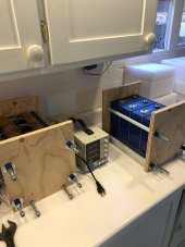
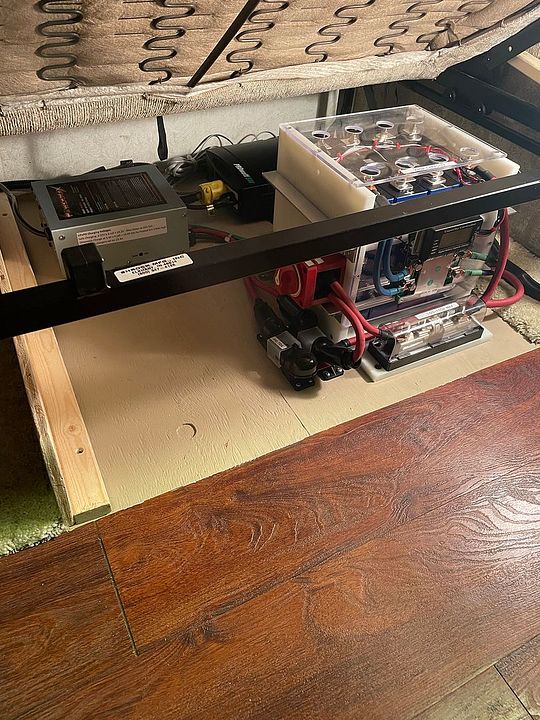
My battery fixture is simply screwed down to the plywood subfloor of the coach - it's solid. It has proper wire sizes and fuses, and feeds run to new and existing buses. An inverter was added, and solar panels and charger, as well as a dc to dc charger in lieu of direct alternator charging from the chassis side. The cells do set on a 1/8" rubber sheet, and the fixture compression rods were simply snugged up to hold it and prevent any battery puffing from charging and discharging.
Here's my finished battery project, with relocated converter/charger and 120V inverter. The battery pack is simply 4ea 230A prismatic cells, with a ClassT fuse and marine type main disconnect. Feed wiring is 2awg - my system BMS is rated for 120A max, so everything is sized to suit.
Here are my replies to your actual questions:
- no specific 'compression' - use a fixture to hold the cells and prevent them from puffing. Something as simple as threaded rods is fine.
- possibly still used threaded rods for fixation using front and back plates OR build a plywood case that holds the cells, tape together with fiber tape - I would not use fiber tape, but the rest makes sense. Plywood is fine, as is StarBoard, what I used.
- use flexible (cable) busbars - Not necessary in a fixture.
- use isolation between cells - something as simple as thin polyethylene cutting mats.
- use paste on cell terminals - Yes, ox guard or similar, and avoid mixed metals as much as possible. For example, no copper to aluminum.
- use a torque wrench on the terminals - yes, you don't want to strip out your terminals, or have them come loose. Nylocks and/or split ring or bite-ring washers where appropriate.
- put the case on rubber mounts (like these) - did not take the link, but rubber isolation isn't critical.


")