diy solar

diy solar

Trailer Solar System - Avoiding Flames...

Pivo

New Member
Joined
Jan 6, 2022
Messages
10
Hello all! I am in the process of building my second solar system for my cargo trailer / RV. It is all Renogy. It includes: 300w solar panels, 40a MPPT charge controller, 1000w pure sine wave inverter, and two 100ah lithium batteries. See the attached picture for the wiring configuration. Does anyone have any suggestions? I am using a Blue Sea Safety Hub 150 for my fuse box instead of a circuit breaker (it can hold 150a MIDI fuses on one side and low amp fuses on the other). I would appreciate any wisdom before I install this system in the trailer. Thanks all!!
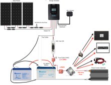

Renogy System Draft 3.jpg
 
Last edited:
Hey Pivo welcome to the forum

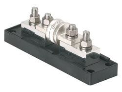
Folks smarter than myself have recommend using a Class T fuse instead of ANL fuse between the batteries and the charge controller.

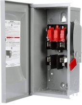
Personally I don't like those red disconnects. I have found items like this for under $50 they are fusible shouldn't melt or crack. Kinda large for a trailer application though.
Siemens SIE GF222NA disconnect.jpg
 
Hey Pivo welcome to the forum

Folks smarter than myself have recommend using a Class T fuse instead of ANL fuse between the batteries and the charge controller.

Personally I don't like those red disconnects. I have found items like this for under $50 they are fusible shouldn't melt or crack. Kinda large for a trailer application though.
View attachment 79702
Thanks very much! Probably too large for my space. I have looked for good quality cut off switches and might have another look around. Renogy suggested the ANL fuse - I will check out the class T fuse as well. Thx for the suggestion!
 
I would not wire it like you have in the diagram. The ANL or Class-T fuse needs to be closest to the battery. I would wire it more like this (adding a bus bar):

battery positive -> main fuse (ANL or Class-T) -> positive bus bar

positive bus bar -> inverter cut off switch -> inverter fuse -> inverter

positive bus bar -> SCC breaker (or SCC cut off switch -> SCC fuse) -> SCC

And if you add the positive bus bar it might be nice to also have a negative bus bar. This way you aren't connecting multiple things directly to the battery terminal. Plus it makes adding a shunt simpler if you decide to do that later.
 
You are welcome.

Another item to consider is the Battery to Charge Controller cable. I think folks like to go larger, like 2 AWG. I also believe the length should be as short as is practical.

I watched a video last night of a lady ("digital mermaid" I think) shorting out her batteries. Scared the daylights out of her but she was uninjured thanks to her Class T fuse.

I suggest reading this thread until you are convinced to use a Class T fuse at the battery.

I have asked numerous questions about WHY I should buy such an expensive fuse and was finally directed to this thread and purchased one.
 
I would not wire it like you have in the diagram. The ANL or Class-T fuse needs to be closest to the battery. I would wire it more like this (adding a bus bar):

battery positive -> main fuse (ANL or Class-T) -> positive bus bar

positive bus bar -> inverter cut off switch -> inverter fuse -> inverter

positive bus bar -> SCC breaker (or SCC cut off switch -> SCC fuse) -> SCC

And if you add the positive bus bar it might be nice to also have a negative bus bar. This way you aren't connecting multiple things directly to the battery terminal. Plus it makes adding a shunt simpler if you decide to do that later.
I like it. (y) Nice one rmaddy
 
Another item to consider is the Battery to Charge Controller cable. I think folks like to go larger, like 2 AWG.
For a 40A charge controller you only need 8AWG.

The inverter wire needs to handle 100A in this setup so that would need at least 4AWG. 2AWG is of course better. All of the battery wires would need to be the same as well.

Larger wires are always fine as long as they physically fit and it does make this easier if you ever plan to increase things. For example, going from 1000W inverter to 2000W.
Excellent point, I was looking at the specs for my "All In One" charge controller which calls for 2 awg, and assuming.

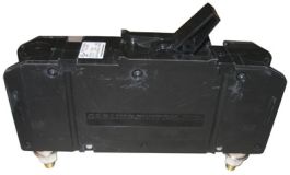
Alternative to fuse + switch.
Rated 50k AIC, so good enough for most any lithium battery.

YIKES $175.00
I need to hit the books to find out what that thing does.
 
YIKES $175.00
I need to hit the books to find out what that thing does.

And that was the unlisted, remote-trip model I linked. (I wondered what the 24V terminals were for)

Here's a retailer, $105 for listed (and no remote trip)


What it does is work up to 125VDC, and interrupt up to 50,000A short circuit current.
Likely both way above your minimum requirement.

What is your battery voltage? I think it is 12V, 2 in parallel.
What is the internal resistance per cell for your batteries? From that (and voltage per cell), I would estimate short circuit current.
There are several fuses, maybe breakers, probably sufficient for that.

People with 48V batteries would generally want class-T, but several cheaper ones rated high enough for 12V and 24V
 
Last edited:
I suggest reading this thread until you are convinced to use a Class T fuse at the battery.
At 12V and even 24V as long as you stay below 200A - my opinion is that a ANL full size Fuse is adequate in combination with a BMS
300A and 400A ANL is dangerous, they don't have enough surface area for the current.

The ANL will react to a fast event - and if it still arks (unlikely) - the BMS will shut of.

150a MIDI fuses
if you want to go MIDI - go with Blue Sea Systems.

My rule of thumb is - as soon as you get to 100A - start thinking about a higher voltage system. As soon as you reach 150A increase the time you think about a higher voltage. 200A - no discussion - that is enough - get a higher voltage.
 
Personally I don't like those red disconnects
If Bussman or BlueSea or the other ABYC compliant brand I forget they are safe as others have indicated here in previous threads.
I’ve never seen a “bad” bluesea product. But you pay for them.
 
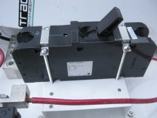
Pretty sure these need 4 long bolts w/ nuts and washers. If you look closely you can see two long channels on the side of the breaker The bolts go through metal saddles above and below the breaker lever and secure to panel from the back of the breaker. I'll try and get a photo of what I'm talking about when it gets light.
 
As by rmaddy in post #4. Except class-t fuse at LiFePo battery positive. Put the device fuses at the positive BusBar, then the switch if wanted. Have a seperate fuse and cable from a positive BusBar to the inverter and additional fuse and cable from BusBar to fuse block.
 
Wow, thanks for the suggestions everyone. I'm soaking it in. A couple things: All of this has to fit into my trailer tongue box (short distances other than from solar panels to the box). The inverter and battery cables are all 4AWG; the fuse block is a Blue Sea Safety Hub 150. I am planning to use a 150A MIDI fuse for the inverter. 10A (or so) on the low amp side of the block for smaller stuff. The cut offs are Blue Sea. The system is 12v. As you can probably tell, I'm a newbie. Just trying to learn.

rmaddy: despite an extra cup of coffee, you lost me (post #4) on a couple things: (1). What does "ANL or Class-T fuse needs to be closest to the battery" mean? After the cut off switch? (I know, I'm slow). (2). I am unclear on the reconfiguration suggestion (i.e. with the bus bar). Is there a way to dumb it down?

Again, thanks so much everyone.
 
Hey Pivo welcome to the forum

Folks smarter than myself have recommend using a Class T fuse instead of ANL fuse between the batteries and the charge controller.

Personally I don't like those red disconnects. I have found items like this for under $50 they are fusible shouldn't melt or crack. Kinda large for a trailer application though.
View attachment 79702
These accept class t rated fuses also...
 
you lost me (post #4) on a couple things: (1). What does "ANL or Class-T fuse needs to be closest to the battery" mean? After the cut off switch? (I know, I'm slow). (2). I am unclear on the reconfiguration suggestion (i.e. with the bus bar). Is there a way to dumb it down?
The main fuse needs to be the first thing connected to the battery. That's what I mean by "closest". Nothing should be between the main fuse and the battery. Everything else comes after the main fuse.
 
The main fuse needs to be the first thing connected to the battery. That's what I mean by "closest". Nothing should be between the main fuse and the battery. Everything else comes after the main fuse.
Where does this come come from?

Put the disconnect first so nothing is energized when the power is disconnected.

A starter (not applicable here) motor can't be fuse so a disconnect can be used. The highest load I've pulled disconnects was probably around 3000A@36V.

Only thing that should bypass the disconnect is the trailer brakes. Which is protected with a fuse
 
Back
Top