diy solar

diy solar

Two questions: Cable lengths and also ground connectors

Wendy

New Member
Joined
Aug 22, 2022
Messages
32
10/8/22

I have two questions…

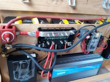
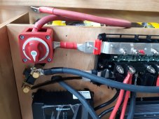
The first is: how critical is the rule that the battery cable needs to be the same length? I have my neg cable going from the far right to the far left to the Victron Energy Sensor bus bar, then from there to the Lynx distributor. (I drew this wire in on the photos, since its not in yet) See photos.
The Positive cable is “nearly” as long total from left side battery to the switch to the lynx distributor. I made an error and forgot to add the length of part of the pathway on the neg cable, so the positive cable is about 5-6 ? Inches shorter. So is that a deal breaker? Do I need to re-cut the red cable for the positive to EXACTLY match the negative cable?

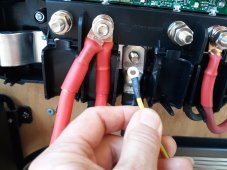
Also, I am trying to connect the tiny ground wire that came with my 3000W Giandel pure sine inverter to the ground post on the lynx distributor. As you can see the connector is tiny and won’t fit a 5/16 lug. I don’t really want to spend $15 on amazon for lot of 14AWG 5/16 lugs. Is there an easy work around? Can I connect something else to the lug and wrap it on the ground post? See photo # 3.

Sorry, I realize these may be lame questions, but I jut want to be able to do these things, but don’t want to be unsafe either. I appreciate your input on both items.

Thanks!
 

Attachments

  • 20221008_180315_edited.jpg
    20221008_180315_edited.jpg
    1.2 MB · Views: 38
  • 20221008_135413_resized.jpg
    20221008_135413_resized.jpg
    387.9 KB · Views: 36
  • 20221008_180259_edited.jpg
    20221008_180259_edited.jpg
    1.1 MB · Views: 36
The length of each wire connected to the positive of the battery to the load and from negative of the battery to the load do not have to be the same since the same the current leaving the battery will be the same current return back to the battery, the long wire will have more Voltage drops than the shorter wire but all the vdrops will all add up to the battery Voltage, I.E. you have 1V Vdrops on 1 ft of the Positive wire, and 0.5V drops on 0.5ft of the Negative wire, so Vrops on the load will be 12V -1.5V = 10.5V, so if you make both cables the same length (still the same total length of 1.5ft of cable) which will be 0.75ft each, so Vdrops on each cable will be 0.75V, that means Vdrops on the load will still be same, 12V - 1.5V = 10.5V.
Your car has battery Negative wire connected to the chassis, then you a bunch of red positive wires going all over your car at many difference length.
When you have batteries in parallel then it matters how you connect the batteries together, length of wires and where you tap off the power if not done properly the parallel connected batteries will not charge/discharge at the same rate..there are many threads about how to properly connect batteries in parallel.
 
Last edited:
The length of each wire connected to the positive of the battery to the load and from negative of the battery to the load do not have to be the same since the same the current leaving the battery will be the same current return back to the battery, the long wire will have more Voltage drops than the shorter wire but all the vdrops will all add up to the battery Voltage, I.E. you have 1V Vdrops on 1 ft of the Positive wire, and 0.5V drops on 0.5ft of the Negative wire, so Vrops on the load will be 12V -1.5V = 10.5V, so if you make both cables the same length (still the same total length of 1.5ft of cable) which will be 0.75ft each, so Vdrops on each cable will be 0.75V, that means Vdrops on the load will still be same, 12V - 1.5V = 10.5V.
Your car has battery Negative wire connected to the chassis, then you a bunch of red positive wires going all over your car at many difference length.
When you have batteries in parallel then it matters how you connect the batteries together, length of wires and where you tap off the power if not done properly the parallel connected batteries will not charge/discharge at the same rate..there are many threads about how to properly connect batteries in parallel.

My batteries will be wired in parallel... so then it DOES matter if they are not the same length?
 
My batteries will be wired in parallel... so then it DOES matter if they are not the same length?
It is matter on wiring the batteries in parallel to make the battery bank, the wires to the load do not matter.
Did you read the link?
 
It is matter on wiring the batteries in parallel to make the battery bank, the wires to the load do not matter.
Did you read the link?
I did just read the link... sorry I did not realize it was there earlier.. I am new to the site and was not aware that the stuff in the blue box below your comment was not just an "auto-added box". lol.
Anyway, I read through it, and you obviously spent a lot of thought on this. I can't claim to understand the majority of the figure information.
I have no idea what "The battery internal resistance is reset to 5 milliohms" means or how you reset it, etc etc for your testing. This dialog is WAY above most of our understanding. ??‍♀️ lol.

I have seen with regularity the diagonal set up on parallel formations in build videos etc. I have seen people say to keep the cables the same length. That is a no brainer for the battery to battery cables, but the cables to the load is my question. It does not look like you have disreagarded that in your diagrams. But it stands to reason to me that if it matters between batteries, it would matter also on cable to the lynx. I just want to get it right so its safe. :)
 
Just my opinion based on my experience.
I keep wire Length & Guage the same from Batt to Inverter.
I run 5 packs in Parallel, each pack has exactly the same length of wire (4/0 AWG) from Pack to common DC BUS. This is to ensure that there is minimal Resistance Difference between the battery packs which is essential for keeping them balanced with equal charge / discharge

I also have a Midnite Solar 250A MNDC E-Panel that contains the WizBangJr Smartshunt, 250A Master Breaker and the other breakers (Solar in, SCC out). The DC BUS goes to a BlueSea 9001e Switch and then to the MNDC, both the (-) & (+) of Equal Length and again from the MNDC Equal Length 4/0 to the inverter/charger. My total wire length from Batt Terminal to Inverter is 14', so to prevent line loss 4/0 was the way to go.

Fusing for each battery pack is on the DC Bus with MRBF Fuses coming off the Busbars.

TIP: Keep the (+) & (-) cables together to prevent magnetic field noise down.
Electro-Magnetic Interference (EMI) and FCC Compliance
• Ensure that the inverter is firmly grounded to the Ground System of the building or the vehicle.
• Locate the inverter as far away from the EMI receptors like radio, audio and video devices as possible.
Keep the DC side wires between the battery and the inverter as short as possible.
Do NOT keep the battery wires far apart. Keep them taped together to reduce their inductance and induced voltages. This reduces ripple in the battery wires and improves performance and efficiency.
• Shield the DC side wires with metal sheathing / copper foil / braiding.
Thanks Steve. I have that planned in my system. Its good to know that is correct. :)
 
Thanks Steve. I have that planned in my system. Its good to know that is correct. :)
When you have more than one battery pack, each pack of battery may be made by parallel or series connected to form a battery pack, I.E. two 12V batteries connected in series to form 24V battery pack, so if you have more than one battery pack connected in parallel, the wires from each pack have to be the same so each battery pack will be charged or discharge equally, it is the same as paralleling battery in parallel to form a battery pack.
You only have one battery pack there is no other battery pack connected to your battery pack right now so no need to worry about the pack being charged or dicharged equally.
May be Steve_S can show the wiring diagram to make it clear about the 'Pack'.
To me battery pack means the pack is made using battery connected in series or parallel as needed to form one battery pack, that is my understanding of battery pack.
 
Last edited:
A Battery Pack: 12V=4 Cells+BMS, 24V=8 Cells+BMS, 48V=16 Cells+BMS. NOT Set in Series or parallel, just standalone batteries.
A Battery Bank: a set of complete independent batteries usually set in Parallel, to increase stored AmpHours. Each Battery can operate independently should any in the bank cutoff for any reason...

* some YT fumblemouths continually say "BANK" when they are talking about a Battery with 16-Cells + BMS (48V Pack) and flip back & forth with terms that only confuse people.

Battery Packs set in series in NOT suggested or recommended, the best option is you buy/build battery packs for the Voltage System you want. Setting in Series have many caveats / quirks.

This is a Bank: 4 battery Packs in Parallel
1665449344931.png
 
Based on pictures of OP setup, it only has one set of batteries connected in parallel with two wires coming out to the buss bar.
Steve's setup has 4 packs in parallel that is why the wires have to be same which is correct.
OP setup:
1665455909653.png
 
Last edited:
Thanks Steve for the clarification... I did not know the difference between bank and pack. My set up is a simple bank of three.

And you are right Bud, I have a battery bank in parallel set up like the above diagram, but only I have three batteries not four.

I am learning. Thanks Steve and Bud for being willing to help. It means a lot to be able to ask and have someone who knows answer some questions.

?
 
Oh, I have a quick question I bet you both know the answer to...
Why do Renogy and Giandal have TWO positive and TWO negative 4AWG cables included in inverter set ups?

I first had a Renogy 2000W inverter and was surprised that it came with two sets of cables, and a fellow I asked about it said you could use BOTH to equate to a heavier size cable.

Then I realized I wanted a 3000W inverter and bought the Giandel inverter... It ALSO had the same set up.

Neither product comes with any kind of installation information that mentions this. Is one set EXTRA? or are they meant to be used in tandem like I have on my photos above. ??

Thanks for your thoughts on this.
 
Are they truely 4AWG?
Most of the wires that come with inverter are cheap and not up to the right size to handle the current even when you double them up, some of them may be copper cladd aluminium wires not pure copper, the crimp on the terminals may be poorly done, etc....
You can use the site to get the idea what wire gauge you need for your inverter, they are also a member of this forum.
Most of the cables that come with cheap inverters should be thrown out with the packing peanuts.
 
Just curious, when talking about batteries in parallel being wired to inverters...is it safe to say that so long as each positive wire between batteries & inverters is the same length, and each negative wire between batteries & inverters is the same length, then it's balanced for charging and discharging? So even if positive and negative cables are different lengths, it's still balanced?

I have 4 sets of 2 batteries in parallel going to the inverter that are networked together through the BMS to act as one bank of 8 batteries. So 4 positive cables going to the inverter, and 4 negative cables. All positive cables are the same length and all negative cables are the same length, but the positive cables are 2' longer than the negative cables.

Since the path of electricity from the inverter to each set of 4 batteries is the same, same resistance, it seems to me that it's balanced. Am I thinking about this the correct way?
 
Back
Top