diy solar

diy solar

Using solar micro inverters with batteries instead of panels

I ran Tesla modules from 43.2 to 47.1V today. Voltage delivered to each IQ7 was probably 1 - 1.5V less due to thin DC wires used as well as a bunch of crocodile clip wires in line, this is where I estimate 0.1 effective resistance between battery and inverters. I can measure exactly tomorrow. IQ7 micros have built in test mode where if you apply grid and PV within 3 seconds they skip the 5 minute wait time and begin feeding power to grid as soon as they boot up. I had 2 ohm resistors in series with each IQ7 during bootup and bypassed those resistors once AC power began to flow out to grid. Everything is controlled manually for now.
Great, thanks.

So you are operating off of a 48VDC battery and your IQ7 / IQ7+ Microinverters integrate a ‘test mode’ which allows you to connect AC and as long as DC is connected within 3 seconds and is connected through a 2 Ohm resistance, it will begin producing output much more quickly / immediately that the ~5 Minutes otherwise required for the full POST / grid signal characterization, correct?

You don’t have any added inline resistance but are estimating ~0.1 Ohm of wiring + contact resistance.

How did you determine a 2 Ohm resistance was required for the first ~3 seconds?

Have you tried and failed with 1 Ohm?

Have you tried and failed with 0 Ohms (of added resistance, meaning wiring + contact resistance only)?

The effective resistance slope of most solar panels is ~1 Ohm, so I’m trying to understand whether 2 Ohms is required or merely boots successfully.

If you could boot successfully with only 0.2 Ohms of inline resistance, would you bother with the complexity of bypassing a boot resistance to get back the ~20W / ~7% in lost efficiency?
 
So you are operating off of a 48VDC battery and your IQ7 / IQ7+ Microinverters integrate a ‘test mode’ which allows you to connect AC and as long as DC is connected within 3 seconds and is connected through a 2 Ohm resistance, it will begin producing output much more quickly / immediately that the ~5 Minutes otherwise required for the full POST / grid signal characterization, correct?
Correct except the bold part. 2 ohm resistor is not required for IQ7 to skip 5 min wait.
How did you determine a 2 Ohm resistance was required for the first ~3 seconds?
Half cell 60 cell solar panel I use is rated 33V 9.5A at MPP so 33/9.5=3.5 ohms. 2 ohms is closest value I had on hand. A bit stiffer than my solar panel but should be fine.
Have you tried and failed with 1 Ohm? Have you tried and failed with 0 Ohms (of added resistance, meaning wiring + contact resistance only)?
Did not try 1 ohm. Tried and ran another IQ7 without resistor at bootup and it ran for multiple days until one day it refused to generate power and kept blinking red light, if I recall.
If you could boot successfully with only 0.2 Ohms of inline resistance, would you bother with the complexity of bypassing a boot resistance to get back the ~20W / ~7% in lost efficiency?
I would not bother. But I don't have Envoy and don't want to risk losing more inverters for now. In the future I plan to install them with solar panels as designed.
 
Last edited:
Further testing confirms that charging during m250 bootup will consistently trigger the DC Resistance error.

This turns out to be an issue also when the AIO’s inverter is operating - discovered when I forgot to turn on the input breaker after adjusting that wiring.

I’ve started putting together a microcontroller to handle startup and shutdown sequencing: an esp32c3 running Micropython measures volts/amps through the m250’s along with temperature at a few points, all as input to a simple state machine ensuring set limits aren’t exceeded. I’ll post code once it’s stabilized.

I’ve also smoked a few v/a sensors discovering that two parallel m250’s give a pretty sizable inductive kick when suddenly shut off. Adding a few TVS diodes, including one 36V chain across the battery inputs, seems to have fixed the issue. Further incentive to pull the old scope out of storage to visualize…

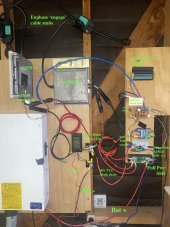
Pic of current layout attached. A proper enclosure will probably happen next month.
 

Attachments

  • IMG_5882.jpg
    IMG_5882.jpg
    176.2 KB · Views: 32
Last edited:
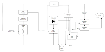
wow, it took 3hours to read this topic... its been a while ago since i posted here... however, its hard to get into the technical details with so much text... To contribute, i tried to draw agt's setup.. And i might also start to experiment with my microinverter. I use 48VDC BB with a NTC-4.0 as a inrush current limiter, but didnt have any u-controller to SSR over,measuring V/A-meter over shunt and, diode chain... but maybe i need to try again but with NTC-10 (16A) combined with a varistor and fuse to protect the u-inverter..

1692213979067.png
 
Did anyone ever reverse engineered the IQ8X-BAT micro inverters?
They are bidirectional and Enphase uses them in everything, even their upcoming V2G EV charger.
They don't do anything by themselves but clearly they can be told to import or export anything from the DC source with some kind of bus system.
Of course, everything grid-tied.

Would be really interesting to be able to control them.
 
Well, 2 of my IQ7 micros I been powering from my 44V battery bank went dead at the same time (solid red light after bootup) after about 400 kWh of energy exported. Been starting them up via 2 ohm resistor and bypassing after AC power would start to flow.
 
Well, 2 of my IQ7 micros I been powering from my 44V battery bank went dead at the same time (solid red light after bootup) after about 400 kWh of energy exported. Been starting them up via 2 ohm resistor and bypassing after AC power would start to flow.
startup outside mppt range, burn with 2ohm resistor until ac power starts..
44v/2ohm= 22A (Imax on microinverter 25A)
44v*22a = 968W
...how do you burn that? using powerresistor? for how long?

Battery voltage will slowly go down, do you prevent the microinverter mppt using boost/buck converter?

Adding a few TVS diodes, including one 36V chain across the battery inputs, seems to have fixed the issue.
how did you arrange those and how many? trying to understand the 36v value.
 
44v*22a = 968W
...how do you burn that? using powerresistor? for how long?
Assuming inverter shorts PV input to check for PV short circuit current this power goes into 2 ohm resistor but for fraction of a second. I think they both failed on restart when my battery was at > 46V due to higher than usual state of charge. It's likely that inverters have bricked themselves due to input overvoltage. Maybe they can be reset via Envoy (which I don't have). I really should have some kind of voltage regulator in line.
 
Hi to everyone, I read most of this thread, but not sure I understand all. So I have an additional questions.
Has anyone tested Hoymiles micro inverters? I don't know if anyone in this forum is from EU. Here we have a law that up to 800W of solar with microinverters can be connected without the permission of the electric provider ( they have to be informed but cannot decline the connection).
So, I'm trying to make the best use of this setup, with 750W solar and HM600 inverter I can theoretically produce about 5kWh but since I have set on 0 emitting my microinverter saves me about 1,5kWh to 2kWh per day, so I'm thinking to add 2kWh battery.
So now I don't know if I can connect hoymiles microinverter directly to a 36V battery pack or is better to24V batery with use DC-DC converter with current limiting?
Thank you for any answer.
Ncsolarelectric has a thread of his own with Hoymiles connected to a battery , however he is much more risk averse and built a custom power limiter board (ie analog power stuff) combined with the zero export DTU . Compared to most people on this thread that just used off the shelf limiters.
 
The microinverter is only being used to discharge battery while producing AC. It doesn't provide charging.

You probably want a system which does both charging and discharging.

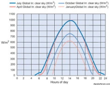
A PV panel connected to inverter only delivers power while the sun is shining, typically peak around Noon and less at other times, for a total of 2 effective sun hours in the depths of winter to 7 effective sun hours in summer, maybe 5 effective hours per day average throughout the year.

1696426923369.png

"Overpaneling" can raise that curve, flattening the top as system clips at inverter's max rating.

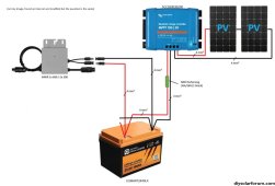
Maybe what you could do is install 5x or so the PV panel wattage, feeding a solar charge controller for a battery. Then feed microinverter from the battery. This way you harvest power five times as fast during the hours of sunshine and backfeed the utilty grid 24/7. A lithium battery would be appropriate for such daily cycling. If it has gross capacity around the wattage delivered per day, it would cycle something less than 100%. Short winter days or overcast it would be drained completely.

A separate off-grid inverter could provide backup power when grid is down.
 
@zanydroid , so de rule is max 600W export to grid, the actual company that maintains the grid, set a limit on the outside meter if even a peak of power reaches 800W of export it switches off the house (and then I have to go to the box where the electric company power meter is and reset it). Actually set up my micro system to soon when the law was 0W export and I have an additional smart meter and DTU, then they relaxed the law, but I don't see any reason to export to grid because in the case of micro system the net metering doesn't apply and you just give free electricity away.
the LXP you suggested seems interesting, but it cost too much (2x the cost of a hybrid inverter).

@Hedges yes the microinverter only discharges the battery, but I have room for max 3 solar panel... so the plan is put 1 panel more and a MPPT charger for batteries and the microinverter runs from the batteries.
So in this thread I understood that some microinverters can work this way, I don't know if Hoymiles HM 600 will work or it will burn?
(I suspect the official reseller won't answer that question, because they are not supposed to)

Added two images for better explanation.
 

Attachments

  • question.jpg
    question.jpg
    386 KB · Views: 12
  • example solar.jpg
    example solar.jpg
    311 KB · Views: 9
If only a couple panels, forget batteries and orient the panels differently but wire in parallel. This should flatten production over more hours.
 
I don't think there's a fundamental reason that LuxPower should cost more than a hybrid inverter other than listing.

(listing = US terminology for "code compliant and (usually) grid operator compliant)

This whole thread is about living dangerously with microinverters... you can consider buying one of the really old ones + power electronics that people on the thread have been OK with.

HM600 is relatively modern and pricey to experiment with.

Or you can import a non-listed hybrid inverter (I don't think it's that much) and convert the full system to DC strings or AC coupled and set self-consume with export limit. I dunno, maybe those SRNE.
 
Also, the LuxPower thing linked above can be thought of as a battery equivalent to a GTIL inverter... you could wait a few months and see if it gets cloned in the unlisted ecosystem for a price similar to a GTIL.
 
Flattening is not a problem, I can add more panels (1 more maybe2). But I hoped that somebody tested Hoymiles microinverters on batteries. Also before I add more panels I have to know if there is a risk that the microinverters don't have a current limiter, because in the manual is written max input current 11A, peak 15A. And I interpreted this as information that if more current is avelible the inverter will draw too much current.

Well if I use a different microinverter it won't work with hoymiles DTU, and also I had to inform my electric grid operator witch microinverter I am using since is working parallel with grid. So I can't just plug any microinverter.

Just additional information about the "law" EU since last year everyone can add so called "mini balcony solar powerplant" power limit is 800W, export/inverter limit 600W. I think if I put more solar panels but maintain the same microinverter that is approved by the grid operator, there shouldn't be any problems. (only question if microinverter can handle it)
 
Most of the designs here use a current limiter because microinverters likely used the intrinsic current limiting capability of solar panels. Including ncsolarelectric’s approach. I believe the difference is that he built the custom limiter module to smooth out the amount of short term charge/discharge stress on the capacitors that a current limited DC DC converter would otherwise slam in as it pulses.

As you see from this thread a lot of people either are not aware about that theoretical issue with capacitors (well it is indeed covered by a spec on these capacitors, so in that sense it’s standard power engineering practice to be mindful) or do not care because they don’t have the capacity to build a custom board.

You could attempt to copy his board, or you can try the limiters used here.
 
Last edited:
So, I'm trying to make the best use of this setup, with 750W solar and HM600 inverter I can theoretically produce about 5kWh but since I have set on 0 emitting my microinverter saves me about 1,5kWh to 2kWh per day, so I'm thinking to add 2kWh battery.
So now I don't know if I can connect hoymiles microinverter directly to a 36V battery pack or is better to24V batery with use DC-DC converter with current limiting?

This is a video where I did a short test to connect a HMT-2000-4T to a 48V/55A power supply.
As you can see, the inverter is limiting the power to ~500W/string by limiting the current it draws from the supply
I think the only time currentlimit on the DC side is needed, is when you connect the DC supply (battery in your case)


Back
Top