I have a U-BMS-LV in hand. Where can I get the CAN bus to USB adapter? (Not the RS485 adapter for talking to the individual modules, I already have that working). And also the CAN software?
this work?
amazon.com
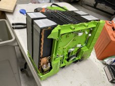
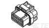
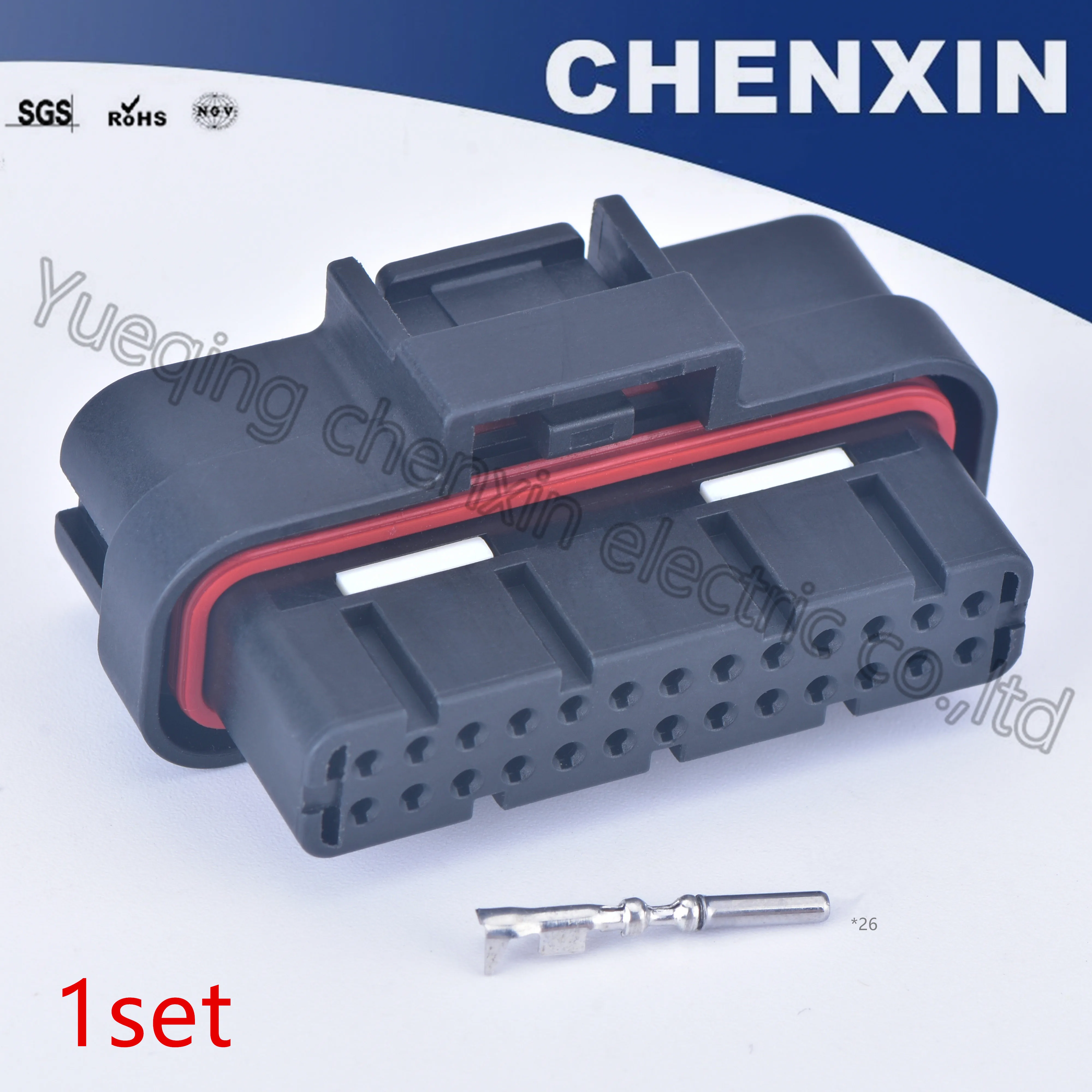
on the bms there are two 26 pin connectors, what are these called so I can buy a plug end to make my wiring harness? The 26 pin IDC connectors with the flat cables look like they might fit but I dont have any handy or a test fit.
this work?
amazon.com
on the bms there are two 26 pin connectors, what are these called so I can buy a plug end to make my wiring harness? The 26 pin IDC connectors with the flat cables look like they might fit but I dont have any handy or a test fit.


")